5
TERMINAL
ONLY
POWERSUPPLY
USEAPPROVED
24VDC 2.5A
REMOTE I/O
RS-232
POWER
ANALYZER/GC
REARVEIWOF COBRASAMPLER
AC INPUT
100-240V
1.5A 50-60Hz
PCSERIAL PORT
COBRA TERMINAL
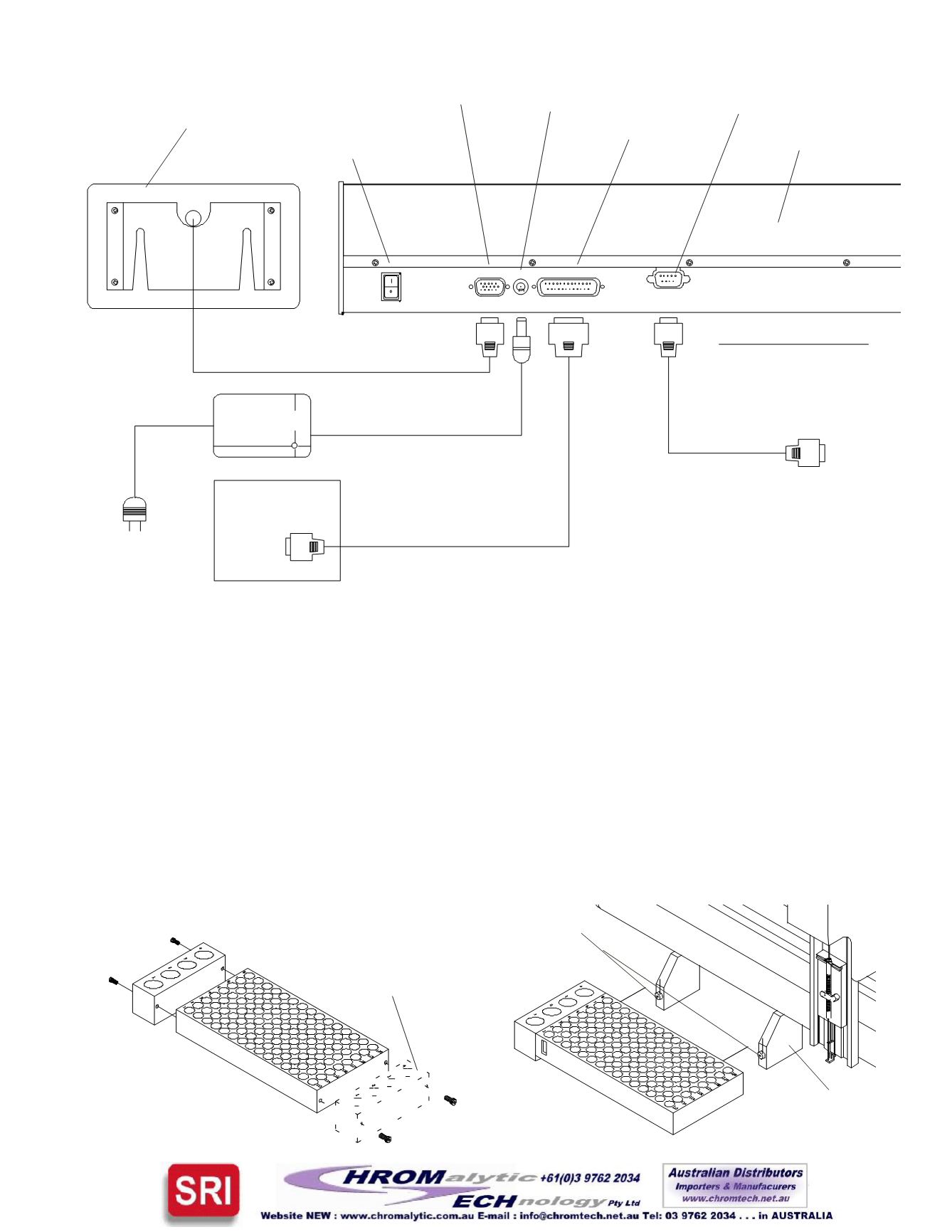
Figure2.0
Rear of
TerminalBox
Rear of Cobra L/S
Figure 2.0 shows the complete installationof cables to theGC and forRS232 remote control.
Be
certainall cable connections aremadebefore thepower to theCobraL/S is turnedon.
Power Switch
TerminalCable
Connector
Power In
Receptacle
Remote I/O
Receptacle
2.6 SampleTray Installation
Unwrap the sample tray andplace it onto the sample traybrackets. The traywill onlymount inone
direction as there are alignment pegs on theholder brackets and corresponding alignment slots in the
tray. Once installed, place an emptyvialwith cap and septa invial position#1 and thewaste / solvent
locations tobe used. Be certain thewaste/solvent tray is locatedon the correct side of the sample
tray for yourGC. Note, thewaste / solvent traymaybe locatedon either side of the sample tray, see
Figures 2.6&2.6 a.
Figure 2.6
Figure 2.6a
Support
Brackets
TrayMount
Pegs
OptionalPosition


