ConnectingGasCylinders
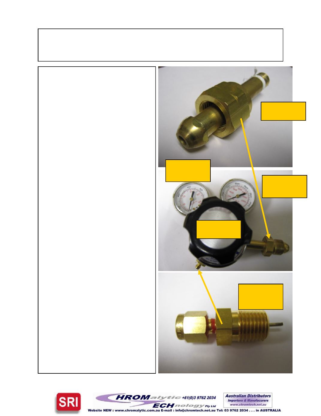
The nuts fit onto the “nipple” of the regula-
tor in order to provide a gas
-
tight seal be-
tween the tank of carrier gas and the regu-
lator. The seal ismade by the round bulb
-
like projectionwhich fits intoa correspond-
ing recess in the top of the gas cylinder.
The threaded end of the nipple screws in-
to the regulator body. The nut and nipple
must match ( have the same CGA num-
ber ).
The cylinder regulator has two pressure
gauges. The right hand gauge shows the
pressure remaining in the cylinder. This
can be as high as 2500psi when the cylin-
der is full. The cylinder should be re
-
filled
when the pressure falls to 200 psi. Don’t
let the cylinder become totally empty since
this will let ambient air contaminate the
inside surfaces. The left hand gauge
shows the reduced pressure supplied to
the outlet of the regulator. This is typically
a pressure of 15
-
90 psi. The knob adjusts
the pressure. Set the cylinder output
pressure 10
-
20 psi higher than the pres-
sure set on the GC. So if the carrier gas
pressure is set to 20 psi using the built
-
in
pressure regulator inside the GC, set the
cylinder output pressure to35
-
40psi.
Regulators used for flammable gases
such as hydrogen or argon/methane
should be equipped with a “snubber” for
safety reasons. The snubber restricts the
flow so that in the event of a total leak
( tubing breaks ) the amount of gas re-
leased is reduced. The snubber fitting has
a very small hole for the gas to pass
through ( .1mm ). Since theGC only uses
small amounts of flammable gas ( 20
-
50
ml/minute ), there is no need for a large
flow rate.
Page2
Nut andnipple
Highpressure
gauge—cylinder
pressure
Lowpressure
gauge—regulator
pressure
Adjustment
knob
Snubber screws
intooutlet fitting
to restrict flow


