Optional Serial Interface
RS-485Option
When the serial port configuration switch is set to the“485”position, the serial port
output is changed to theRS-485mode. If theactuatorhashadan ID setpreviously,
that IDwill be recalledand retained. Otherwise, the IDwill be set to the factorydefault
valueof“Z”.
Note:All RS-485communicationsusean IDandmustbeprecededwitha ‘/’:
i.e,
/ZVR
<enter>
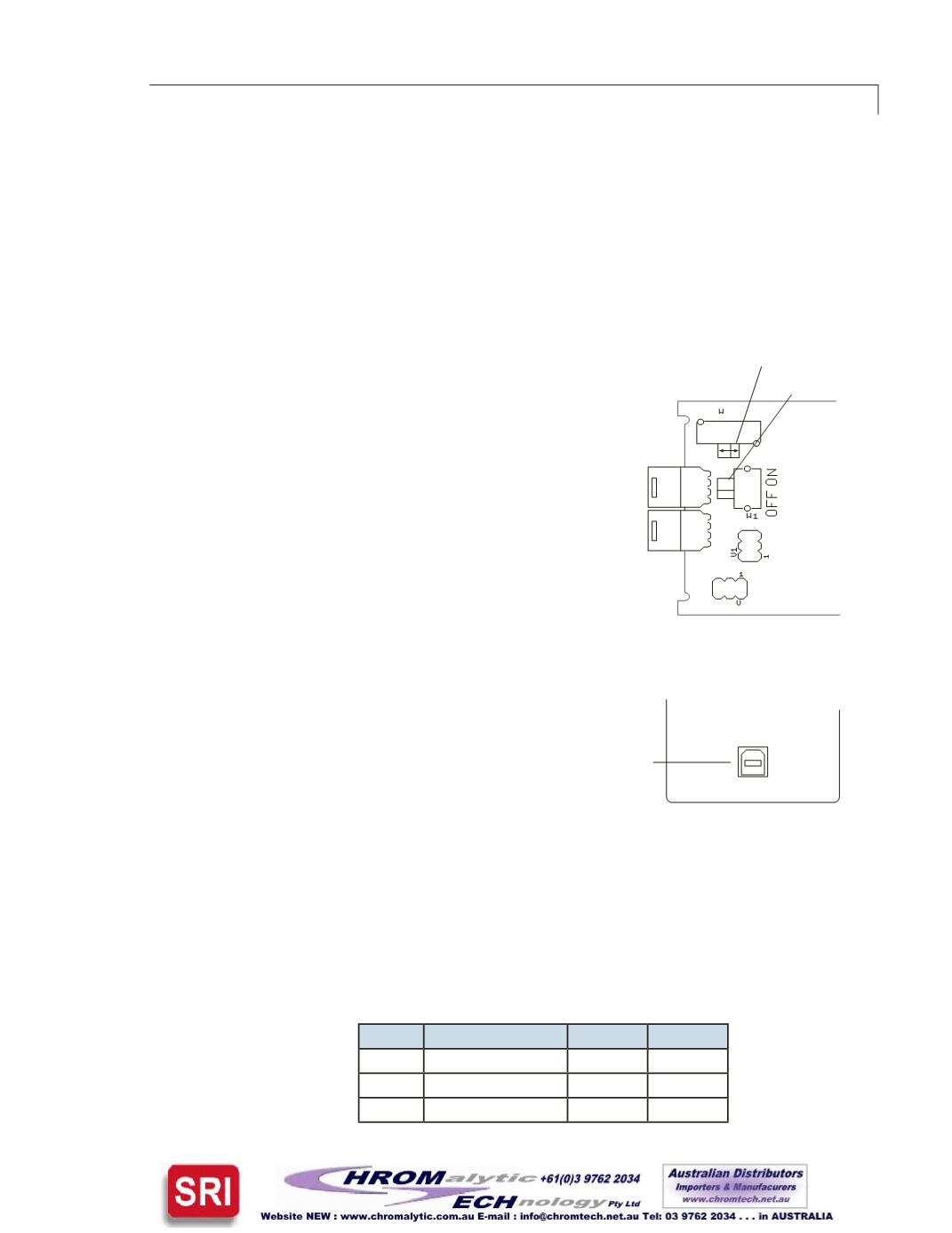
Setting theSerialPortConfigurationSwitch
1. Remove the4 screws from the front (valve side) of the
actuator.
2. Carefully slide theassemblyoutof theenclosure. We
recommend that theenclosurebeopened ina static-
freeenvironment followingall proper ESDprotection
techniques.
3. Locate the slide switchmarked“232<––>485”,and set
it to485.
Note: The switch labeled“TerminationOn<––>Off”is
typically left in theOffposition.Unless thewiring from
thehost control to thedevice isvery longand it is the last
deviceat theendof a signal chainofdevices, it is recom-
mended that this switch is left in theOffposition.
USBOption
TheUSB interface installsasavirtual COMport
(VCP). TheVCPdriver causes theuniversal actua-
tor toappear asanadditional COMport available
to thePC,soapplication softwarecanaccess the
actuator in the sameway it accessesa standard
COMport. Refer to“AppendixA: InstallingUSB
Drivers”,onpage21.
Serial CommunicationProtocol
Serial communication isbasedonanASCII stringprotocol.CarriageReturn (ODhex) and
LineFeed (OAhex) charactersparse thecommunicationsbydefining theendof each
command. A three-pinconnector isused for the serial interface:pinassignmentsare
indicatedbelow.Softwareflowcontrol (Xon/Xoff) andhardwarehandshakingarenot
supported.The tableon thenextpagedescribesandexplainsall thecommandsavailable.
A fuller explanation follows.
Pin #
RS-232
RS-485 DB9*
1 Ground
Ground
5
2 Transmit to host
B (+)
2
3 Receive from host
A (-)
3
*ForVICI cable I-22697
��
��
� �
�
� �
�
�
�
��� ���
Serialport
configurationswitch
termination
switch
Figure9:
Serial port
configuration swithch
���
���
����������
Figure10:
USBconnector
on rearpanel


