16
OptionalBCD Interface
Hardware Input /OutputProtocols
Thedigital interface ismade througha
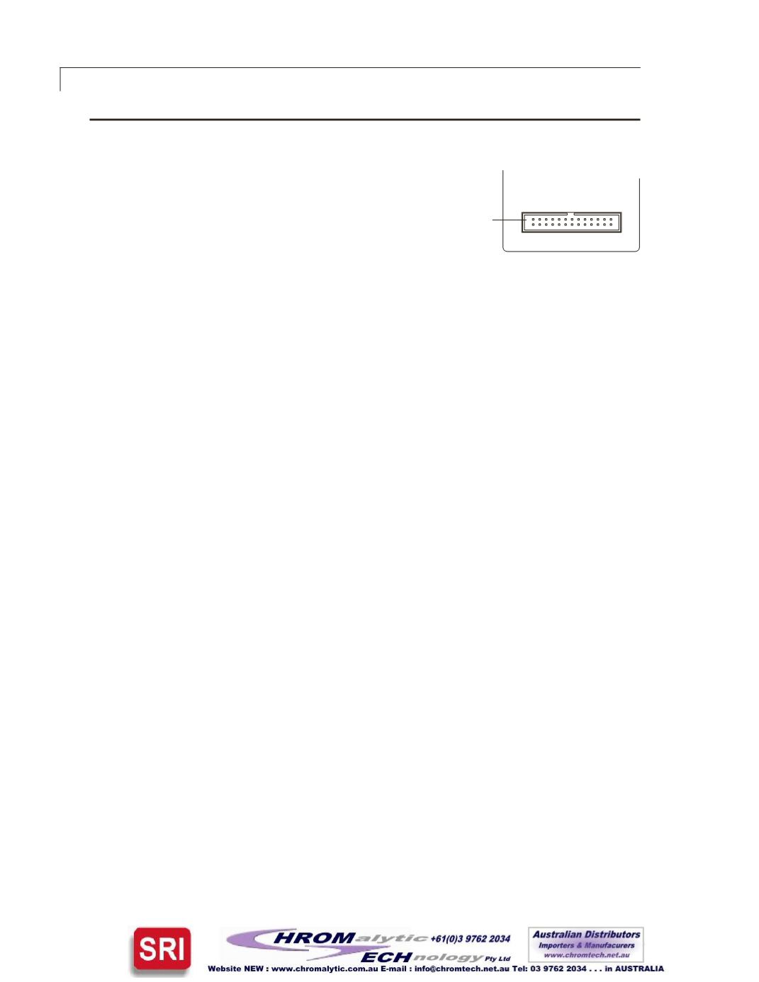
26pinconnectorwhichalsoprovidespower
(+5volts/100mamaximum) andgroundout-
puts. Theground shouldbeconnected to the
control system tomaintaincommonality
between theactuator and thecontrolling
device. If you intend toprovideyourownpower supply,
make sure that ithasan isolatedoutputor that it sharesa
commongroundwith thecontrolling system.
Digital input/output control of theactuator isdesigned for simplicityandflexibilityof
function. The simplest control of theactuator canbeaccomplished inmodes1and2
witha singlecontrol line for theSTEP function. Mode3 requiresonly twooutput control
lines–STEPandHOME.Thecharton thenextpage listsothercontroloptions.
The inputsareheld toa logical high (+5volts)bypull-up resistors,andaredesigned to
bedriven loweitherbycontact closure,5voltdigital logic,oropencollector transistor
outputs. The signal polarity isdefinedas“negative true”–asserting the signal involves
shorting the signal (in thecaseof contact closure) ordriving it (in thecaseof logicor
transistor signals) towithin0.8voltsofgroundpotential. These input signalsmustbe
at least 30milliseconds induration.
Theoutputsarealso“negative true”signalsdrivenbystandardhighspeedCMOSgates,
capableofdrivingstandard logic inputgates.They include theBCDposition,motor run,
rotationaldirection,anderrorsignals.If theactuatorstopsoutofpositiondue toastuck
valve,theBCDoutput isset to“0”(all lineshigh foranegative trueoutput).
Digital InputProtocols
The inputmodesare selectedduring factory setup/programming.
BinaryCodedDecimal (BCD) inputmode (default)
For the96possible inputpositions,all 8digital inputdata linesare required.Refer to the
charton thenextpage for the signal linedefinitions.
Parallel InputMode
In thismode, thedata input linesare redefined so that each input lineequates toonly
oneactuatorposition;anyandall combinationsofdata input linesare invalid.Thismode
can supportonly8positions:1BCD=position1;2BCD=position2;4BCD=position3;
8BCD=position4;10BCD=position5;20BCD=position6;40BCD=position7;and
80BCD=position8. Theoffset valueSO is set to1,and since thenumberofpositions
is limited to8,anyuser-setNPvaluegreater than8will revert to8. (See thecharton the
nextpage formoreexplanationofNPandSO.)
Binary InputMode
Thismodeallowsup to128possible inputpositions. All 8digital inputdata linesare
required. Refer to thecharton thenextpage for the signal linedefinitions.
�����������
�����������������
����������
Figure11:
Digital I/O
connectoron rearpanel


