6
SettingUp theChallengeVolume
Thestudy lookedat sixdifferent challengevolumes:0.2,1,5,10,
20, and 100 Liters. The 0.2-Liter volume simulates the small
samplevolumeused inmost purgeand trapapplications. The1,
5 and 10 Liter volumes are typical sample volumes used in
thermal desorptionapplications (1,2). Thehigher volumesof 20,
and100-Literswerechosen for two reasons. First, itwill provide
users additional information if they need to use larger sample
volumes to increase detection limits by increasing their sample
size (volume).Second,youcanuse these largersamplevolumes
to differentiate one adsorbent from another. An example of this
wouldbeauser that needs toobtaina10 liter sampleof analyte
X. He/she can use the performance charts to compare the
adsorbents and choose the one that has good recoveries that
extend into20or100-Liter range.Bychoosing theadsorbent that
hascapabilitiesbeyond thedesiredsamplevolume, theusercan
safely assume they have chosen the appropriate adsorbent.
Table 4
shows the challenge volume parameters used in this
research.Thechallenge flow rateof0.05Liter/minwasconstant.
TheAnalysisMatrix
With twenty-four different adsorbents to test, six different vol-
umes for each adsorbent, and two desorptions of the same
adsorbent, this matrix adds up to over 288 analysis excluding
calibration and blank tubes. To minimize the effect of storage
timeon recovery,weconducted theanalysisandpreppingof the
tubes in fiveseries,asshown in
Figure4
.This reduced theeffect
of storage time, since theanalysisof the first tube to the last tube
spanned less than 5 hours.
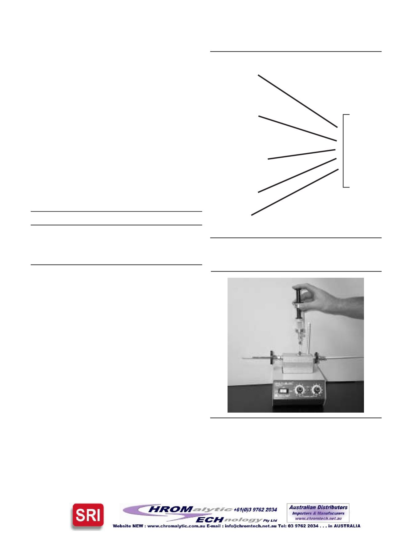
Spiking theTest GasMixon theTubes
We introduced the 43 analyte gas mix onto each adsorbent
packed tube by using the technique of flash vaporization. This
wasconductedbyusingaprototypedevicedevelopedbySupelco
that is presently named the “Adsorbent Tube Injector System”
(See
Figure 5
). This device incorporates a Swagelok
®
union
fittedwithvespel/graphite ferrules that connected the inlet of the
tube toaglass injectionchamber fittedwithaseptaport.Ablock
of aluminum surrounds the glass injection chamber. This trans-
fers the heat of the Multi-Blok
®
Heater to the glassware. A
continuous flowof cleannitrogensweeps the injectionchamber.
Wemaintained the nitrogen flow rate for this research at 0.05L/
min using a constant flow controller.
A20mLsyringevolumeof theundiluted43-analytegasmixwas
injected into the septum port of the glassware while nitrogen
swept the test mix onto the inlet of the tube that was at ambient
temperature.After4minuteshadelapsed,we removed the tube.
The 0.2 Liter volume of nitrogen was enough to completely
sweep the test mix onto the adsorbent contained in the tube.
Series 1
GlassBeads
CarbopackF
CarbopackC
CarbopackY
CarbopackB
CarbopackX
Series 2
Carboxen-563
Carboxen-564
Carboxen-569
Carboxen-1000
CarbosieveS-III
Series 3
Coconut Charcoal
PetroleumCharcoal
SilicaGel Grade 15
PorapakN
Chromosorb 106
HayeSepD
Series 4
Carboxen-1001
Carboxen-1002
Carboxen-1003
Series 5
Tenax TA
TenaxGR
Carboxen-1016
Carboxen-1018
Challenge
Volumes
Set 1
0.2 Liter
Set 2
1 Liter
Set 3
5 Liter
Set 4
10 Liter
Set 5
20 Liter
Set 6
100 Liter
However, for the other five volumes studied, we physically
removed the tubes from theAdsorbent Tube Injector andplaced
them into one of the six-ports of aDynatherm tube conditioner.
Wechose theDynathermSix-tubeconditioner toprovide the rest
of the challenge volumes. The Six-tube conditioner has six
individualports that the flow ratecanbecontrolled independently
(See
Figure6
). Eachof the flowportswere set todeliver 0.05L/
min.
(Only the pneumatic section of this devicewas used, at all
times during the challenge volume the packed adsorbent tubes
remained at ambient lab temperatures
).
Table4. TheChallengeVolumeParameters
Challenge Volume Challenged FlowRate Challenge Time
(Liters)
(Liters/min)
(hours)
0.2L
0.05L/min
4min
1L
0.05L/min
20min
5L
0.05L/min
100min
(1 hr 40min)
10L
0.05L/min
200min
(3 hr 20min)
20L
0.05L/min
400min
(6 hr 40min)
100L
0.05L/min
2000min
(33 hr 20min)
Figure4. TheAnalysisMatrix
Figure5. SupelcoAdsorbent Tube Injector System
(spiking the test gas ontoa tube)


