Table II
Sulfur compoundsused to test
the inertnessof aSulfinert® treated system.
TurningVisions intoReality
™
800-356-1688 • 814-353-1300
20
YEARS
Sulfinert
®
-TreatedSampleCylinders
IncreaseStorageTime forActiveSulfurCompounds
APPLICATIONS
NOTE
Stainless steel sample cylinders commonly areused in the collection and
analysis of refinery andnatural gas samples.These samples often contain
trace amounts of sulfur-containing compounds (e.g., hydrogen sulfide,mer-
captans, and sulfides),which can interferewith reactions or poison catalysts
inmanypetrochemical processes. Because sulfur compounds quickly react
with stainless steel surfaces, accurate determinationof these compounds is
impossiblewhenusinguntreated sample cylinders.
Restek’s Sulfinert
®
passivation technique bonds an inert silica layer into the
surface of the stainless steel.This layer acts as a barrier, preventing active
compounds from reactingwithor adsorbing to the stainless steel.Therefore,
Sulfinert
®
products are ideal for storing and transferring reactive sulfur com-
pounds.Most stainless steel products canbe treatedwith Sulfinert
®
passiva-
tion, including tubing. Because the Sulfinert
®
layer is incorporated into the
structure of the stainless steel, treated surfaces canbe bent or flexedwithout
affecting the inertness characteristics (Table I).
We developed a gas chromatographic analyticalmethod todemonstrate the
effects of using Sulfinert
®
transfer lines, sample loops, and sample cylinders
for sampling, storing, and analyzing low-level reactive sulfur compounds.To
characterize Sulfinert
®
surfaces,we tested the stabilityof sulfur compounds in
three Sulfinert
®
sample cylinders over a 54-hour period.Table II lists the test
compounds and their concentrations.
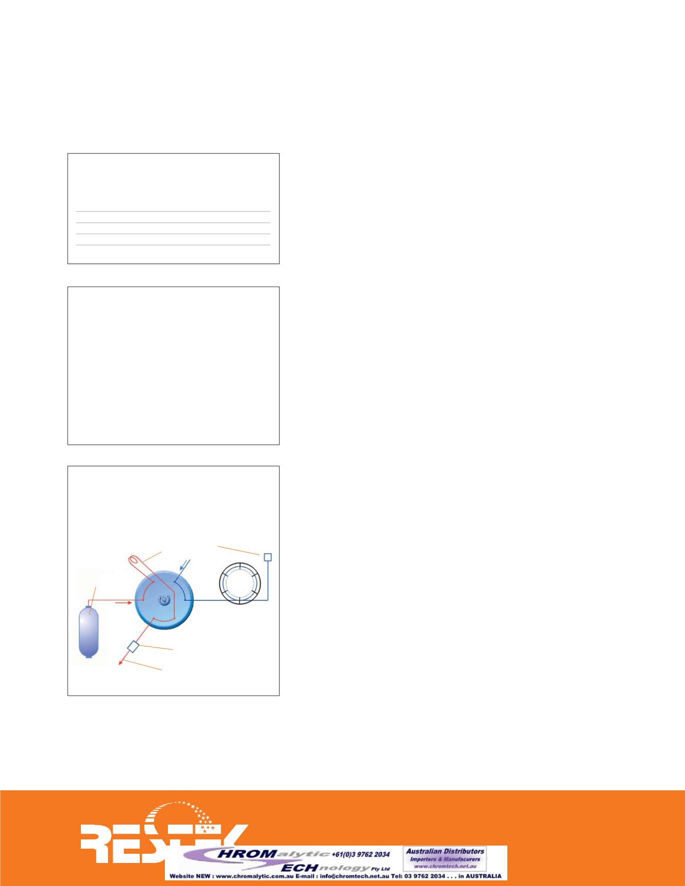
AnalyticalSystem
The analytical systemwasdesigned so that a17ppbv standard couldbedetect-
edwith sufficient sensitivity toquantify compound loss. Sample introduction
was with a 1mL Sulfinert
®
sample loop, Sulfinert
®
Valco
®
valve, and 1/16-inch
Sulfinert
®
transfer lines (Figure 1). The analytical column was connected
directly to theValco
®
valve.
In order to control transfer of the sample to the 1mL sample loop, an orifice
was attached to the exit of the sample loop. This allowed a controlled flow in
the range of 60-120mL/min. during sample transfer (flowwas pressure-regu-
lated from the samplecylinder).AnRtx
®
-1column (60mx0.53mm,7µm) and
a Sieversmodel 355 sulfur chemiluminescence detector (SCD)wereused.
1mL of a 1000ppbv standardwas added to a 500cc sample cylinder andpres-
surized to 160psig. The sample was prepared “dry” (no water added to the
cylinder) to simulate a petrochemical process. Dimethyl sulfide, which has
been shown tobenon-reactive in thismixtureand isnot adsorbedby stainless
steel,was used as an internal standard.
To introduce the sample onto theGC column, the sample loopwas flushed
with sample for 45 seconds, then the cylinder valvewas closed and the sam-
ple loopwas vented to atmospheric pressure.TheValco
®
valvewas switched
to introduce the sample from the loop to the analytical column, and the
analysiswas started. Figure 2 (page 2) shows the chromatogram.
Compound
Formula Stock Conc. Cylinder Conc.
(ppbv)
(ppbv)
hydrogen sulfide
H
2
S
1000
17
carbonyl sulfide
COS
1000
17
methyl mercaptan
CH
3
SH
1000
17
ethyl mercaptan
CH
3
CH
2
SH 1000
17
dimethyl sulfide*
CH
3
SCH
3
1000
17
dimethyl disulfide CH
3
SSCH
3
1000
17
* internal standard
Table I
Minimumbend radius for
Sulfinert®-treated tubing.
TubingOD
MinimumBend Radius
≤
1
/
16
"
1" (2.5cm)
1
/
8
"
2" (5.1cm)
1
/
4
"
4" (10.2cm)
Figure I
Analytical system for detecting
lossesof active sulfur compounds.
Sulfinert
®
sample
cylinder
orifice= 0.0060"
Rtx
®
-1 analytical
column
Sulfur Chemiluminescence
Detector
1mL Sulfinert
®
sample loop
exit


