System Operation
57 of 82
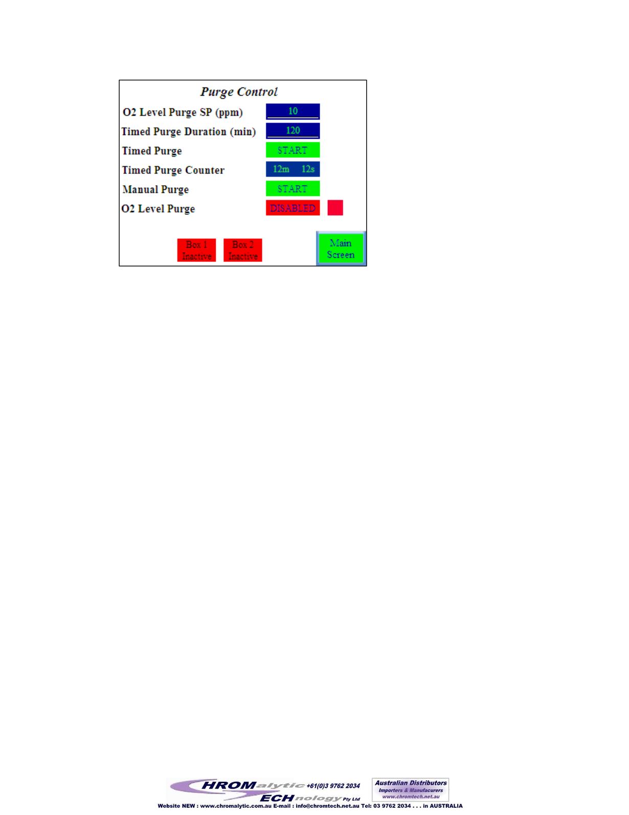
Figure 54 Purge Control screen
5.15 Solvent Removal Systems
Various sizes of solvent removal systems are available. These are optional extras that can absorb
solvent vapors that would otherwise contaminate the purification media.
5.15.1 Large Capacity Solvent Removal
There are three isolation valves labeled A, B, and C. The isolation valves dictate the flow of box
atmosphere, routing it directly to the purification column or through the solvent removal column
prior to the purification column. There are arrows on these valves, indicating the direction of
flow through them. To open them, turn the black knob counterclockwise. To close them, turn
the black knob clockwise.
The evac/refill valve is located on the front of the unit. To the left of the valve is a pressure
gauge that indicates the pressure inside the solvent removal column. Evacuate will open the
solvent removal column directly to the vacuum pump. Refill will expose it to the box
atmosphere as well as the incoming working gas supply.
5.15.2 Opening the Solvent Removal Column
1
Refill the column by turning the evac/refill valve to refill until the pressure gauge has
returned to 0, and then close the valve.
2
Open isolation valves B and C.
3
Close isolation valve A. It is important that B and C be opened prior to A being closed so
that flow to the blower will not be interrupted.
4
The flow of box atmosphere is now passing through the solvent removal column prior to
passing through the purification column.
142


