System Control Electronics
67 of 82
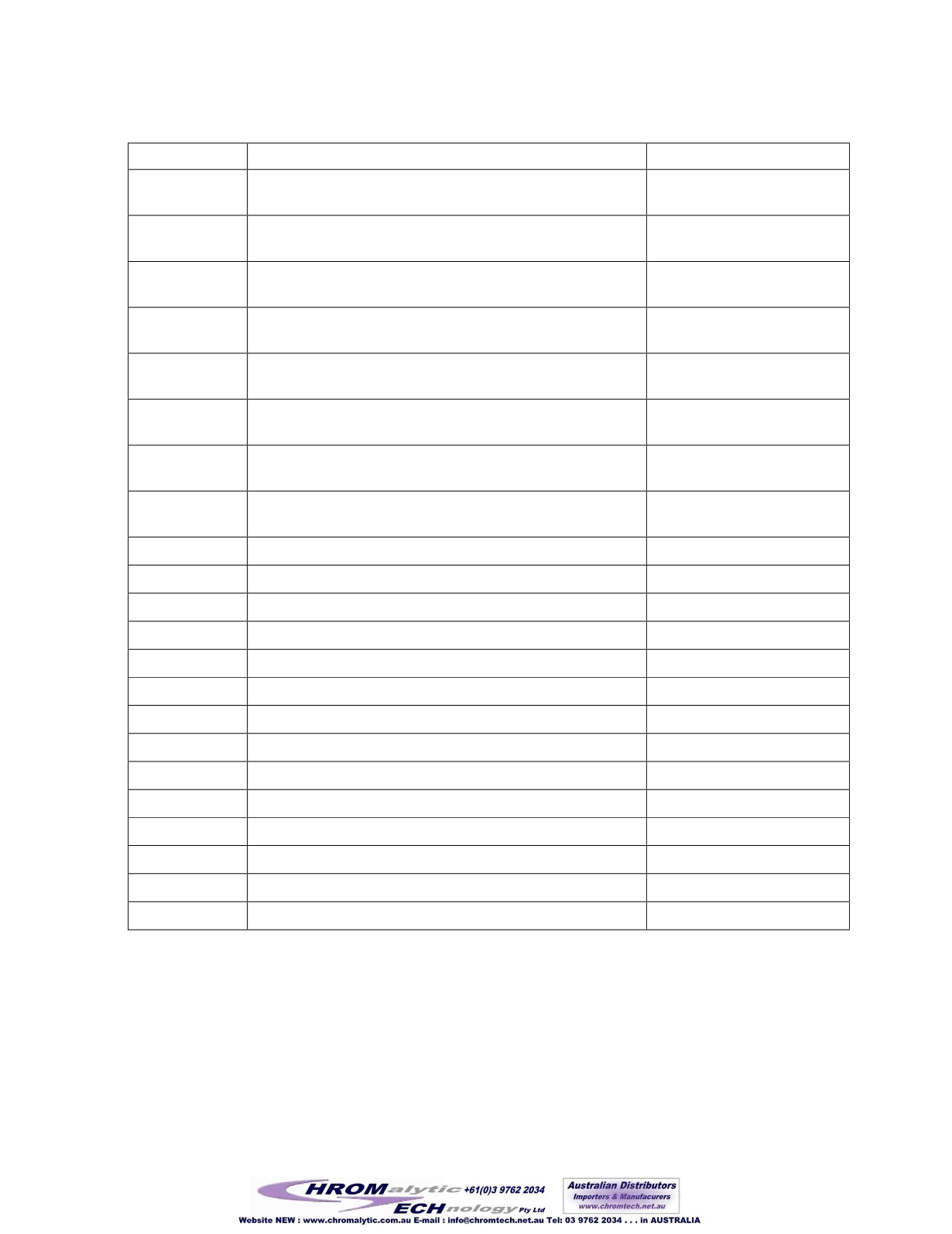
Table 2 Relay Functions and Connections
Connector
Function
Connection
GAS
Gas valve, opens the box to the working gas source,
increases box pressure.
Valve block, GA
VAC
Vacuum valve, opens the box to the vacuum pump, reduces
box pressure.
Valve block, VA
AE1
Antechamber 1 evacuate, opens the chamber to the vacuum
pump.
Antechamber 1
AE2
Antechamber 2 evacuate, opens the chamber to the vacuum
pump.
Antechamber 2
AR1
Antechamber 1 refill, allows the Antechamber to refill from
the box.
Antechamber 1
AR2
Antechamber 2 refill, allows the Antechamber to refill from
the box.
Antechamber 2
BL1
Blower, activates the column 1 valves to enable the blower
speed control to turn on the blower.
Column 1 valves
BL2
Blower, activates the column 2 valves to enable the blower
speed control to turn on the blower.
Column 2 valves
CO1
Cooling, vents column 1.
Valve block, CO
CX1
Column 1 flow control, used in dual column systems.
Dual column in-line pipe
CX2
Column 2 flow control, used in dual column systems.
Dual column in-line pipe
EX1
Regeneration gas exit, column 1.
Main cell block, EX
FRZ
Freezer control.
Freezer Power Crydom
HTR
Heater control.
Furnace power Crydom
HT1
Heater control, column 1.
Heater Crydom
HT2
Heater control, column 2.
Heater Crydom
PG1
Automatic purge valve control.
Purge valve
PMP
Vacuum pump control.
Vacuum pump Crydom
RG1
Regeneration gas, opens column 1 to regeneration gas.
Valve block,RG
RG2
Regeneration gas, opens column 2 to regeneration gas.
Valve block,RG
RV
Regeneration vacuum, opens column 1 to the vacuum pump. Valve Block RV
PG2
Automatic purge valve control.
Purge Valve
8.2.3.1 Solid State Relays
This section of the board is where the PLCcontrol lines activate or deactivate the solid state
relays (SSR’s). These SSR’s then switch on and off motors and heaters in the system.
152


