I
n sample injections into a hot splitless injectionport liner, a typical 1µL sample expands to a volume of hundreds
ofmicroliters.
1
The sample solvent vapor, and the analytes, fill the entire injector system. During sample expan-
sion, analytemolecules come in contactwithhot, active surfaces outside the injectionport liner, andoccupy the
deadvolume at the bottomof the injectionport, below the inlet endof the
column (Figure 1). In splitless injectionmode, there is very little carrier
gas flow in this area to carry the analytes backup to the column inlet.
This situation ismost noticeablewith active compounds that degrade
when they come in contactwith active surfaces; recoveries canbe signifi-
cantly reduced. In addition, late-eluting compounds that donot readily
vaporize are affectedby injectionport discrimination.
The innovative geometry of aDrilledUniliner
®
inlet liner minimizes
active sites in the sample pathway, and reduces injection port discrimi-
nation. The analytical column connects to the bottom of aDrilled
Uniliner
®
inlet liner via a Press-Tight
®
seal (Figure 1), eliminating sam-
ple contact with any part of the injector below the column inlet.
Recoveries of active analytes are significantly improved.
2
Additionally,
the hole in the side of the liner allows the injector to be operated in tra-
ditional split/splitlessmode.
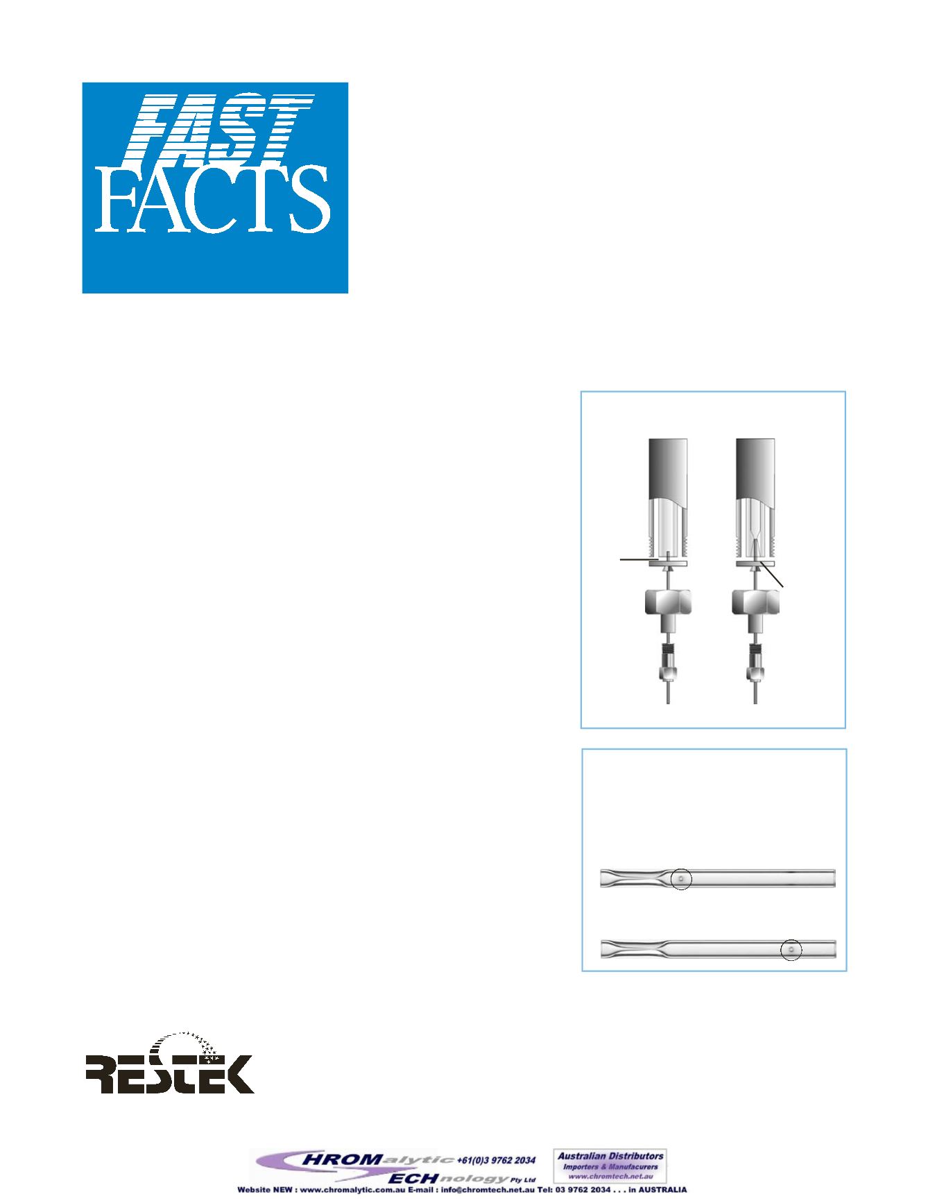
Restek offersDrilledUniliner
®
inlet liners in two configurations (Figure
2). The liner to use depends on the analysis, and how closely the early-
eluting compounds elute to the solvent peak.
In flash on-column injections, all of the solvent is transferred from the
injector to the column, producing a substantial solvent peak tail.
Splitless injection eliminates the solvent tail, because the injector goes
into the splitmode after the compounds of interest are transferred to the
column, and all solvent remaining in the injection port is flushed out
through the purge vent. The solvent peak ends abruptly, as shown in
Figure 3a. Elimination of the solvent peak tail is an advantage to using
the splitless injection techniquewhen analyzing compounds that elute
close to the solvent.
ADrilledUniliner
®
inlet liner produces a distinctly different solvent peak
shape than the single gooseneck splitless liner, as shown inFigure 3. Themost noticeable difference is the peak
width; the peak is considerably narrower than the peak from the single gooseneck liner. The position of the hole in
theDrilledUniliner
®
also affects solvent peak shape.ADrilledUniliner
®
with the
hole near the bottom produces a sharply ending solvent peak, similar to that from a
single gooseneck liner (Figure 3b). This liner is a direct replacement for a splitless
liner, and should be usedwhen analytes elute closely behind the solvent.
At-a-Glance Product
Information fromRestek
800-356-1688
●
814-353-1300
MinimizeAdsorptionofActive
Analytes,UsingaDrilled
Uniliner
®
GC InletLiner
TwoConfigurations, toMatch
ChromatographicConditions
Analytes
contact hot
surface and
dead volume
at base of
splitless
liner
Figure 1
—
Inlet liner geometry affects
analyte recovery.
Drilled
Uniliner
®
inlet liner
efficiently
transfers
sample onto
column
Use hole near top configuration if analytes elute later than
the solvent peak, or when the sample solvent iswater
Figure 2
—
DrilledUniliner
®
inlet liners
are available in two configurations. The hole
allows the injector to be operated in
split/splitlessmode.
Use hole near bottom configuration if analytes elute near
the solvent peak
Continued


