Operating theSRI AutomaticCalibrationAccessory
( ACS )
Both “zero” and “cal gas” are controlled
byashut-off solenoid located inside the
GC. When the “zero” gas solenoid is
actuatedbyPeakSimpleand thepres-
sure is 10psi, the flow rate through the
mixing chamber andout the sampling
“tee” is1000ml/minute.
When the “cal gas” solenoid is actuated
and theEPCpressure is10psi ( con-
trolledby the channel 2pressurepro-
gram ) the flow rate is about 10ml/
minute. TheEPCpressure canbe var-
iedbetween0.01and99.99PSI. The
actual flowof “cal gas”will dependon
thebalancegas the “cal gas” is sup-
plied in. If for instance thebalancegas
is helium the flow ratewill be higher
than if thebalancegas is air. Theop-
eratormust physicallymeasure the “cal
gas “ flow rateat different EPCpres-
sures.Measure the flowat theoutlet of
the sampling “tee”.
Thedilution ratio is the flowof “cal gas”
dividedby the flowof “zero” gas. So for
example if the “cal gas”was10ppmof
BTEXand the flowof “cal gas” was
10ml/minuteat anEPCpressureof
10psi, thedilution ratiowouldbe
10/1000or 100. The10ppmBTEX
would be diluted to 100ppb. Amixing
chamberwitha volumeof about 100ml
is located in the thermostatted valve
oven toensure completemixing. The
diluted andmixed gas flows through the
sampling “tee” displacingambient air.
The vacuumpumpwhichnormally
sucks about 100ml/minute through the
traps thenpulls thediluted “cal gas” in-
steadof ambient air.
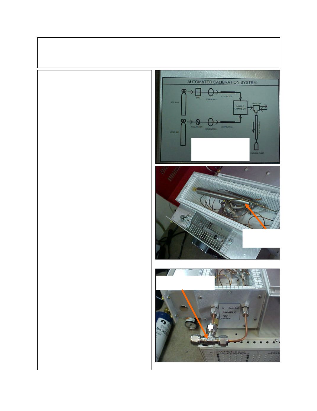
Mixing chamber located
in valve oven
Sampling “tee”
This diagram is printed
on the top of the valve
oven
Page 2


