


 121 / 628

 www.restek.com
119
Fused Silica Capillary & PLOT
Column Ferrule Guide
GC COLUMNS |
PLOT COLUMNS
PLOT Column Selection
www.restek.comSee what makes Restek’s
new
Rt®-Silica BOND
column the best on the
market! ............
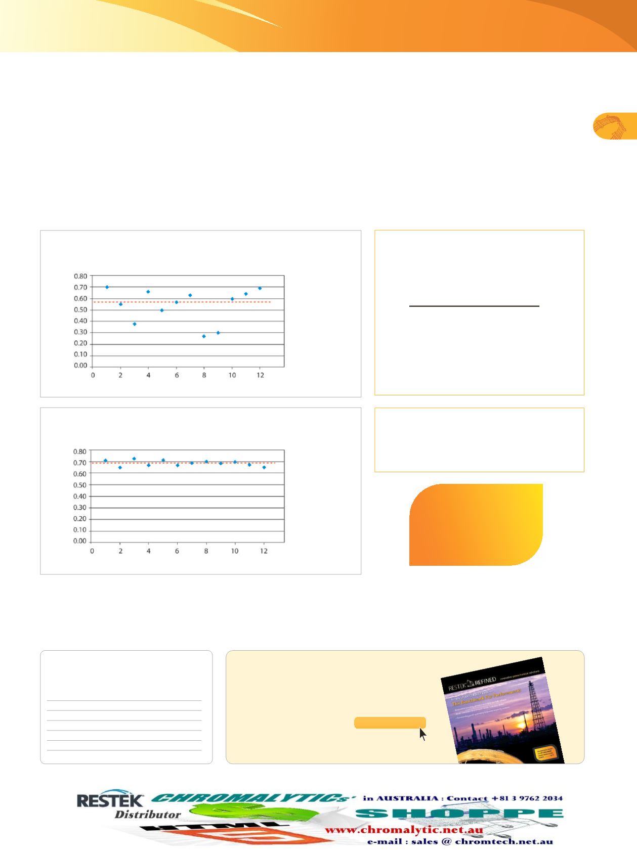
. page 120Figure 4:
PLOT columns from Restek offer consistent flow
restriction, giving more reproducible results column-to-column.
Figure 3:
Traditional PLOT columns show significant flow variability,
indicating inconsistent column coating thicknesses.
In order to measure flow restriction reproducibility, Restek introduced a new factor: the flow restriction factor (F). This factor is
based on the retention time of an unretained marker compound, as measured on both coated and uncoated tubing using the same
backpressure setting (Equation 1). For quality control purposes, methane is used as the marker when evaluating porous polymer
columns, and helium is used for testing molecular sieve 5A columns.
Flow restriction factor determination can be used to assess both the degree of column restriction and the reproducibility of the
column coating process. Flow restriction can also be calculated (Equation 2). Figure 3 shows typical results for PLOT columns
manufactured using a conventional process. Because of the difference in flow restriction, individual columns have very different
flow characteristics. In contrast, Figure 4 shows results for columns made using our Rt®-QS-BOND (bonded porous polymer) PLOT
column process. Clearly, Restek’s manufacturing process results in greater consistency in both column coating thickness and flow
restriction, which results in more stable retention times and better performance in Deans and related flow switching techniques.
Flow restriction factors are specified on the certificate of analysis (CofA) included with every Restek® PLOT column, and the values
are listed on the report.
Equation 1:
Flow restriction factor (F) is
used to demonstrate coating consistency.
Restek’s PLOT columns are exceptionally robust, featuring concentric stabilized coating layers. They allow for more consistent gas
flows and are recommended for applications sensitive to variation in retention time or flow. These PLOT columns are a significant
advance in technology and are ideal for efficient, reproducible analyses of permanent gases, solvents, and hydrocarbons.
Equation 2:
Percent flow restriction of
coated column.
% restriction = (1–F) x 100
t
R1
of unretained component
(uncoated tubing)
t
R2
of unretained component
(coated column)
F =
Number of Columns
t
R
= retention time
Note: F values will always be <1 as the coated column always
has more restriction than the uncoated column.
F
F
Number of Columns
GC Column ID
Ferrule ID
0.15 mm
0.4
0.18 mm
0.4
0.25 mm
0.4
0.32 mm
0.5
0.53 mm
0.8
free literature
Restek’s PLOT Column Family
The New Benchmark For Performance!
Download your free copy from
lit. cat.# PCBR1163D-UNV