


 141 / 298

• 15 •
www.restekcorp.com800-356-1688
by Brad Rightnour and Michael Goss, Instrument Innovations Team
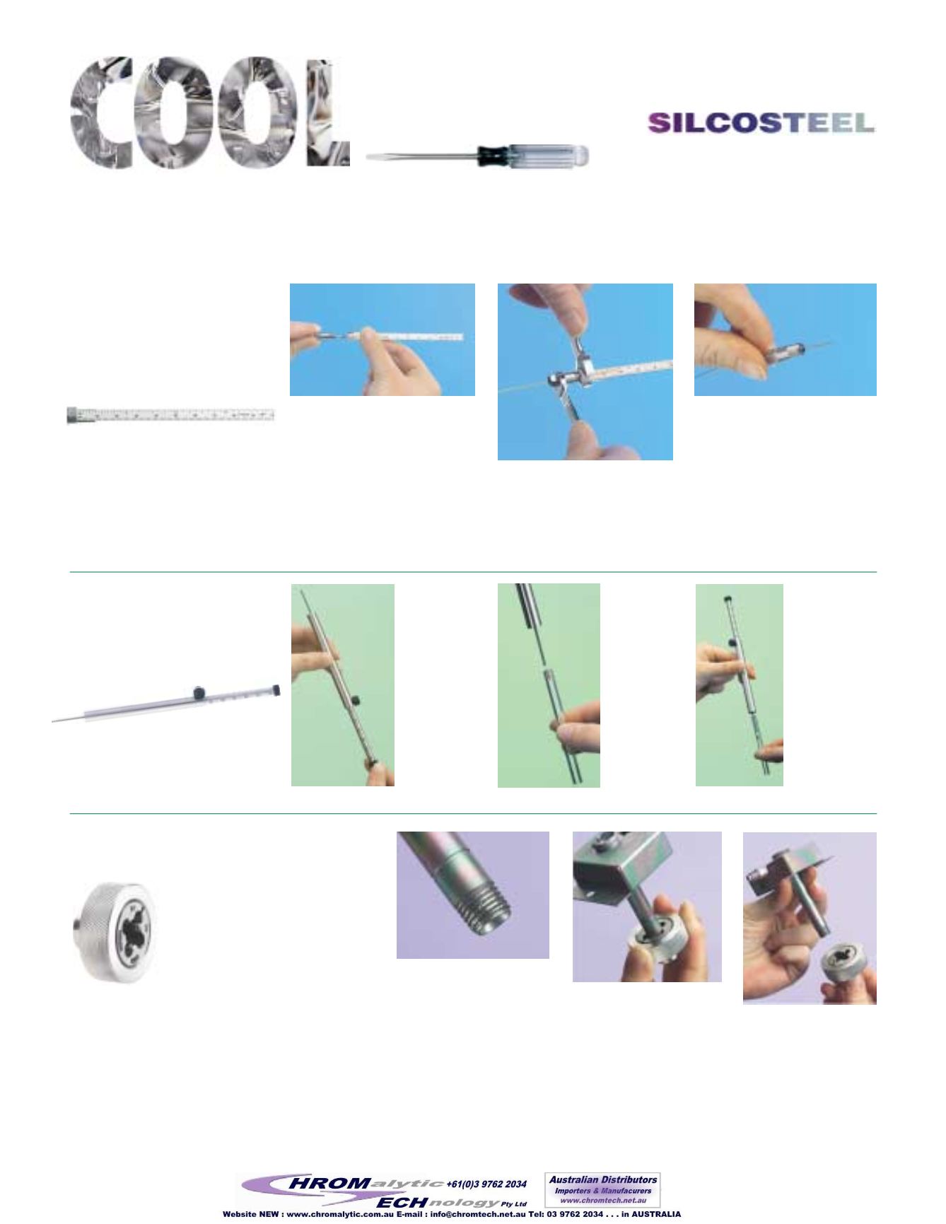
Rethreading Tool
Achieve a better seal!
✔
Save the cost of replacing
expensive injectors!
✔
Repair worn or damaged threads.
For
1
/
16
" compression fittings (thread
size, 10-32):
cat.# 23016, (ea.)
For
1
/
8
" compression fittings (thread size,
5
/
16
-20):
cat.# 23017, (ea.)
For
1
/
4
" compression fittings and Agilent-style split/split-
less injection ports (thread size,
7
/
16
-20):
cat.# 23018, (ea.)
For Varian injection ports:
cat.# 23019, (ea.)
Capillary
Installation
Gauge
Easily pre-seat ferrules for
consistent installations!
✔
Pre-seats ferrule onto column for
consistent installation distances.
✔
Made from high-quality stainless steel.
For Agilent-style fittings
(0-100mm from
front of ferrule)
:
cat.# 21034, (ea.)
For
1
/
16
" fittings
(15-115mm from back of
nut):
cat.# 21399, (ea.)
Install the column nut and ferrule
onto the capillary column. Cut the col-
umn end squarely to prevent ferrule
particles from entering the column.
Slide the column into the installation
gauge to the recommended insertion
distance as specified by the instrument
manufacturer. Finger-tighten the col-
umn nut at the correct distance.
Using a
5
/
16
" wrench on the installa-
tion gauge nut and a
1
/
4
" wrench on
the column nut, tighten the assembly
with moderate force to ensure a
properly seated ferrule.
With the same wrenches, loosen the
assembly and remove the column
and column nut with seated ferrule
from the installation gauge. The fer-
rule should be properly seated in the
column nut, and the column should
remain in place when light force is
applied. If it slides loosely in the fer-
rule, repeat steps 1 and 2.
1
2
3
Loosen the
nut on the
side of the
tool to
adjust the
gauge to the
manufactur-
er’s recom-
mended
depth.
Place a one-
centimeter
plug of
loosely
bound wool
at the top of
your inlet
liner. Be
sure to wear
gloves when
handling
glass wool.
Insert the liner
packing tool
completely into
the liner until
the tool bottoms
out. Remove the
tool. The wool
is now posi-
tioned correctly
in the liner and
ready for use.
Due to constant installation,
removal, and exposure to
extreme temperature changes,
threads on GC parts easily
become worn and damaged.
This can cause a poor seal,
and oxygen can enter the sys-
tem, compromising analytical
results and possibly destroying
expensive analytical columns.
Screw the rethreading tool
completely onto the injection
port in a clockwise direction.
Depending on the severity of
thread damage, this may
require force.
Unscrew the rethreading
tool and inspect the
threads. Repeat as neces-
sary. When done, wipe
clean with methanol to
remove any debris.
1
3
t oo l s
Try These New Tools from Restek for Easier
GC Maintenance
Try Restek’s
Injection Ports
For more information, request the catalog
Genuine Restek Replacement Parts for
Agilent GCs
(lit. cat.# 59627B).
Inlet Liner
Packing Tool
Easy and reproducible!
✔
Position wool correctly every time.
✔
Accurate to a specific, measured depth
(0-100mm).
cat.# 20339, (ea.)
1
2
3
2