GCMAINTENANCE
Replacing theColumnOvenFanMotor
7. Remove the new bearing/armature assembly from the newmotor. Insert it into the center of the
existingmotor and press it into place. Replace the cap and tighten the two black screws.
8. Replace the aluminum plate and plug in the fan.
9. Replace theGCbottomcover and rock theGCuponto itsbase. Secure thebottompanelwith its six
screws.
10. Lubricate thenew fan impeller and setscrewwithanti-seizecompound. Attach thenew impeller to
themotor shaft protruding through theoven floor. When the setcrew is tightened, it locks intoadimple
on the shaft. Replace the screen, reshaping it if necessary.
6. Use your SRI screwdriver to pry the bearing/armature assembly
from the fanmotor.
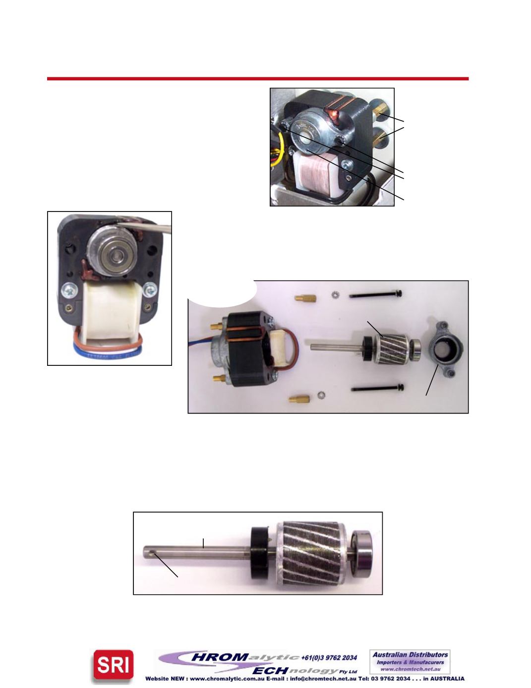
5. The ovenmotor is secured to the chassis with
four brass stand-offs. The bearing/armature
assembly issecured to theovenmotorby twoblack
hexhead screws throughacap. Usea1/4”wrench
to hold the stand-offs while unscrewing the black
hex head screws to remove the bearing/armature
assembly. Takecarenot tobreakor twist thescrews.
Once the screws are loose enough, the cap comes
off andyoucan see thebearing/armatureassembly.
Brass stand-offs
Black hex head
screws
Cap
Dimple
Fanmotor shaft
Disassembled
fanmotor:
Bearing/armature assembly
Cap


