DETECTORS
Photo Ionization Detector - PID
Theory of Operation
TheSRIPIDdesignusesa10.6eV lamp
withahighvoltagepowersupply. Sampleladen
carriergasflowsfromtheanalyticalcolumninto
the PID sample inlet, where it is streamed
through a 100µL flow-through cell. When
samplemolecules flow into thecell, theyare
bombardedby theUV lightbeam. Molecules
withan ionizationpotential lower than10.6eV
releasean ionwhenstruckby theultraviolet
photons. These ionsareattracted toacollector
electrode, thensent to theamplifier toproduce
an analog signal, which is acquired by the
PeakSimpledatasystem.
UnlikeotherPIDdesignsthatheattheentire
lamp,only the lampwindowof theSRIPID is
heated. This results ina longer lamp life for
SRIPIDdetectors.
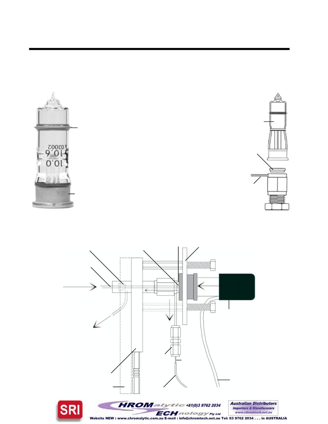
10.6eVPIDLamp
(SRI Part #8670-1242)
Anode
ring
Cathode
base
SimplifiedPIDOperationalDiagram
Teflon
TM
seal
(SRIpart#
8670-1244)
PID lamp
Collector
inlet
Sample-laden
carrier gas
inlet (from the
column oven
on 8610 &
310 GC’s, or
the heated
transfer lineon
110models)
High voltage band inside
the black plastic hood
(must make contact with
the lamp anode for PID
operation; do not adjust
unless themainGCpower
is turnedOFF)
Collectorelectrode
signal cable
Collector
electrode
support
union
Heaterblock
PIDhigh
voltage
lead
UV
light
100µLPID
detector cell
Spring-loaded
retainingplate
Ionsare
attracted
to the
collector
electrode
Teflon
TM
seal
Collector
electrode
PartialPIDAssembly -
Exploded View
Analytical
column
Columnovenwall
Ferrule
ThePIDcell effluent flowsaround the
column back to the PID sample gas
outlet, which is connected to the next
detector in series or vented to
atmosphere inside thecolumnoven
NOTE: The end of the
column must be visible in
the detector cell when the
PID lamp is removed from
the retainingplate. Itshould
beapproximately1mm from
the lampwindowwhen the
PID lamp is inplace.


