7
Figure 4.
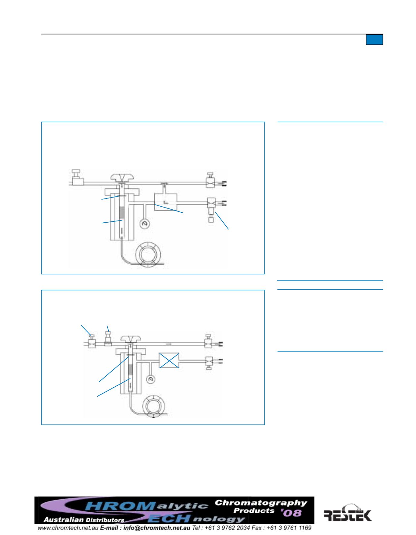
Splitless injection flowpaths in a typical headpressure-regulated system.
throttling
valve
carrier inlet
injection port
o-ring or
ferrule
injector
liner
solenoid
valve
needle
valve
septum
purge vent
split vent
pressure
regulator
needle
valve
Figure 3.
Splitless injection flowpaths (injector purge off) in a typical
flow-controlled/backpressure-regulated system.
flow
controller
carrier
gas
inlet
injection
port
o-ring or
ferrule
injector
liner
3-way
solenoid
valve
needle
valve
septum
purge vent
split vent
backpressure
regulator
closed
Figure 3.
• Solenoid valve closed between injector
and split vent: only column flow enters
injector; column flow passes into column.
• Needle valve at septum purge vent allows
only septum purge flow to exit septum
purge vent: most of carrier gas diverted
through solenoid valve, out through split
vent.
• Sample vapor in injector liner can exit
only to column, mixedwith column flow
of carrier gas.
• Solenoid valve switched to establish
flowpaths as in split injection: sample
vapor remaining in injection port swept
out of split vent.
• Splitless hold time determined by sample
composition.
to detector
analytical
column
Figure 4.
•
Solenoid valve closed: entire carrier gas
flow and entire sample directed onto
analytical column.
•
Carrier gas flow rate into system reduced
to enable entire flow to pass through
analytical column.
to detector
column
closed
Operating in the Splitless InjectionMode
When operating in the splitless injectionmode (Figures 3 and 4), the solenoid valve is
switched, changing the flow path of the carrier gas.At the beginning of a splitless injection,
the solenoid valve is set to prevent the flow of carrier gas from the injection port body through
the solenoid valve.When the solenoid valve is in this position, only the column flowmoves
through the injection port liner. Column flow rate is determined by the pressure of the carrier
gas in the injection port as set by the pressure regulator and the analytical column dimensions.
After a carefully determined time (the splitless hold time) the solenoid valve is switched to
re-establish the flow paths as used in the split injectionmode. This allows any vaporized
sample remaining in the injection port to be quickly swept out of the injection port liner
through the split vent.A typical splitless hold time is between 60 and 90 seconds. The ideal
splitless hold time is long enough to allowmost of the vaporized sample in the injection
port liner to be transferred to the analytical column. Excessively long splitless hold times
can produce tailing peaks and broad peaks. The splitless hold timemust be determined
through experimentation, andwill vary according to sample composition, column length and


