Chapter: MODEL110GCCHASSIS
TOpiC:
HEATEDTRANSFERLINE
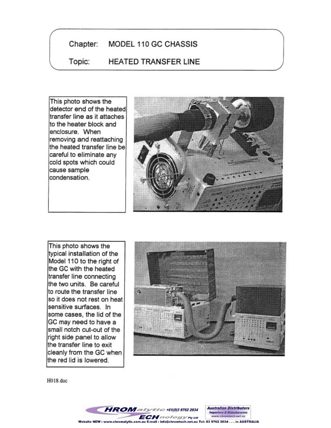
is photo shows
the
detector end of the heated
transfer line as it attaches
to the heater block and
enclosure. When
removing and reattaching
he
heated transfer line
be
careful to eliminate any
cold spots which could
cause sample
condensation.
lThis photo shows the
typical installation of the
Model 110 to the right
of
theGCwith the heated
transfer line connecting
he
two
units. Be careful
to route the transfer line
so it does not rest on heat
sensitive surfaces, In
somecases, the lid
of
the
GCmay need to have a
small notch cut-out
of
the
right side panel to allow
the transfer line to exit
cleanly from the GCwhen
the red lid is lowered.
HOl8
doc


