Chapter:
Topic:
MAINTENANCE
Testing The Signal Input ofThe Serial Data System
The SRI serial
port
data system is equipped
with
four channels of precision data acquisition.
In
fact, the signal inputs available on the serial
port
data acquisition interface offer the precision of a
digital voltmeter.
Any
0
to
5VDC detector signal may be connected
to
anyone of the channel inputs,
and the millivolt reading
will
be
displayed on-screen. This reading should match the readings of any
precision meter connected
to
the same input. No special calibration of detector signal inputs is
required.
If
it
does becomes necessary to verify the precision of the serially-interfaced signal inputs, the
following procedure
will
permit easy confirmation.
In
order
to
confirm the precision of the signal inputs, temporary electrical connections are
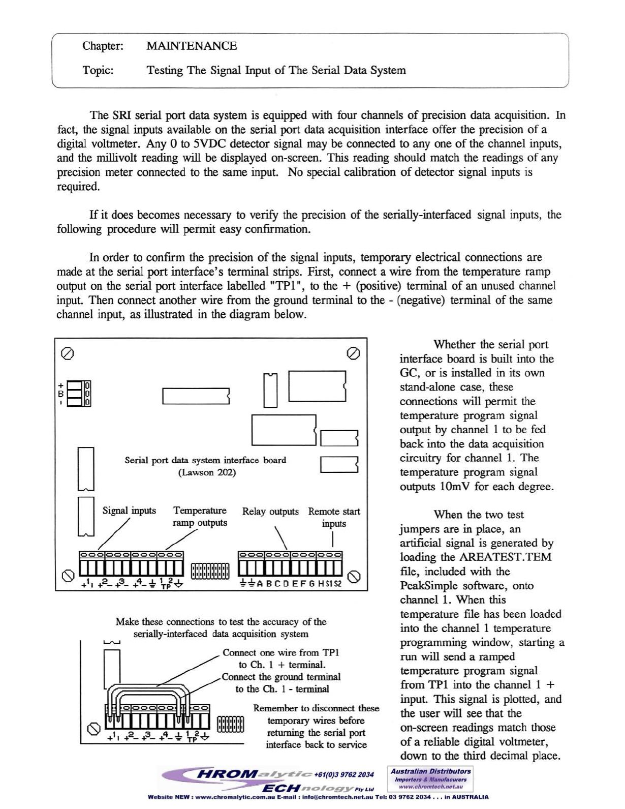
made at the serial
port
interface's terminal strips. First, connect a wire from the temperature ramp
output on the serial port interface labelled "TP1",
to
the
+
(positive) terminal of an unused channel
input. Then connect another wire from the ground terminal to the - (negative) terminal of the same
channel input, as illustrated in the diagram below.
Make these connections
to
test the accuracy of the
serially-interfaced data acquisition system
Whether the serial
port
interface board is built into the
GC, or is installed in its own
stand-alone case, these
connections will permit the
temperature program signal
output by channel 1 to be fed
back into the data acquisition
circuitry for channel 1. The
temperature program signal
outputs lOmV for each degree.
When the two test
jumpers are in place, an
artificial signal is generated by
loading the AREATEST.TEM
file, included with the
PeakSimple software, onto
channel 1. When this
temperature file has been loaded
into the channel 1 temperature
programming window, starting a
run will send a ramped
temperature program signal
from TPI into the channel I
+
input. This signal is plotted, and
the user will see that the
on-screen readings match those
of a reliable digital voltmeter,
down
to
the third decimal place.
o
Remote start
inputs
I
Remember
to
disconnect these
temporary wires before
returning the serial port
interface back to service
Relay outputs
\
[Ij]jj]jjjjjj
t -tABCDEFGHS1Sl 0
Connect one wire from
TPI
to Ch. I
+
terminal.
Connect the ground terminal
to the Ch. I - terminal
Serial port
data
system interface board
(Lawson
202)
o
o
D/mp~
7=
ITIIJjjjjjjjJ
"''''''' '
I'C'\
" " , " , "
o...Y
1 2 3 4 .1. 1 2-.L
+
I
+
- +- +-""
Tp v
o
+81
B 0
,
0


