6
•
800-356-1688
III.Preparing theSamplingTrain forUse
The sampling trainmust beprepared in the laboratorybefore it canbeused in
the field. The trainmust be assembled and leak tested, the flow ratemust be
set, and the train must be certified clean. All of the following information
shouldbe documented for the chainof custody for the passive sampling train
and the sample collectedwith it.
Assemble, LeakTest, andSet theFlowRateof thePassiveSamplingTrain
Choose the critical orifice (Table II, page 3) according to the sampling period
and flow rate you anticipate using (Table III). Thiswill ensure an accurate and
valid sample.There shouldbeamarkingon theoutsideof thecriticalorifice fit-
ting indicating the sizeof theorifice. Inacleanenvironment, assemble the sam-
pling train components as shown inFigure 2 (page 2). It is imperative that you
leak test the assembled train. If the sampling train leaks during sampling, the
final pressure in the canister will not be the desired final pressure,making the
sample invalid.Themost common reason for invalid samples is leakswithin the
sampling train.There are twoways to leak test the train:
1. Pass helium gas through the flow controller anduse a sensitivehelium
leakdetector to test for leaks (e.g.,RestekLeakDetector).
or…
2. Cap the inlet, attach the sampling train to an evacuated canister, open the
valve on the canister and evacuate the sampling train.Then, close the
valve andmonitor anypressure change in the static sampling train. Leaks
of less than1mL/min. canbe detected in1-2minutes.
This is a goodpractical test—the small internal volumeof thepassive sam-
pling train, combinedwith even a small leak,will produce a large change in
monitoredpressure.According toEPAMethodTO-15, thepressure change
shouldbe less than2psig (13.8kPa) over a24-hour period.
After you are certain the sampling train is leak-free, set the desired sampling
flow rate.
Toset thedesired flow rate follow thesesteps:
1. Remove the protective cap from the backof theVeriflo®FlowController
SC423XLbody.
2. Connect either an evacuated canister or a vacuum source to the outlet of
the sampling train.
3. Connect ahighquality calibrated flowmeter (i.e.,mass flowmeter, rotame-
ter,GC-type flow sensor [e.g.,RestekProFLOW6000ElectronicFlowmeter,
cat.#22656]) to the inlet of the train.
4. Apply vacuumbyopening the canister or turningon the vacuum source.
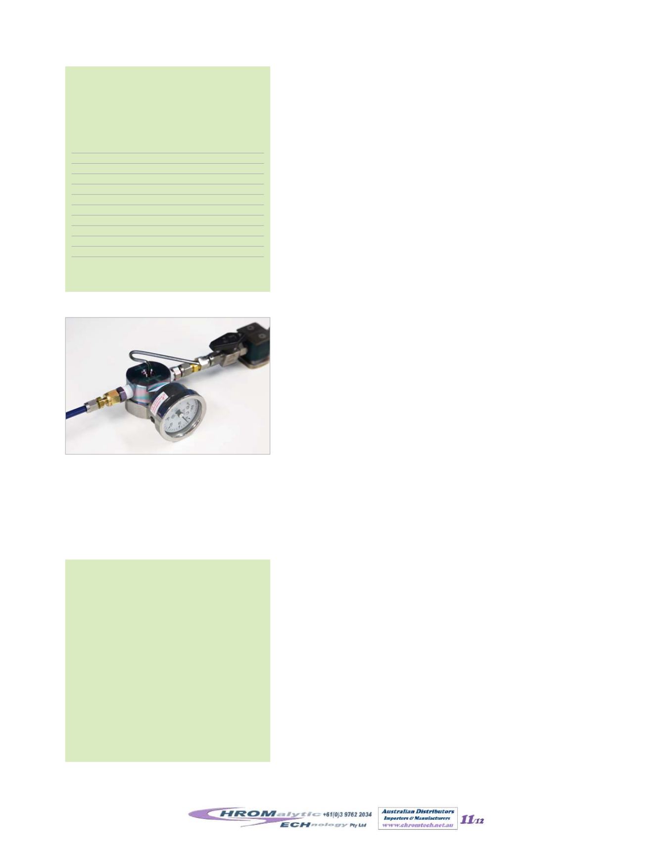
5. With a 3mmhex (Allen®)wrench, adjust the piston gap screw to achieve
the desired flow rate (Table III). Between adjustments allow the flow to
equilibrate for severalminutes. See Figure 8.
6. Replace theprotectivecaponto thebackof theVeriflo®FlowControllerbody.
Cleanliness:Certifying theSamplingTrain forUse
US EPA CompendiumMethod TO-14A/TO-15 requires that the sampling
trainbe certified cleanprior touse. Certify the trainby passing a humidified,
high-purity air stream through the train, concentrating the exit gas on a trap,
and analyzing the gas by gas chromatography/mass spectrometry or other
selectivedetector.For the sampling train topasscertification theanalytical sys-
tem shouldnot detect greater than0.2ppbvof any targetVOC.
The certified sampling train shouldbe carefullypackaged in aluminum foil or
in a clean container for storage or for shipment into the field.Care inpackag-
ing is critical. Careless handling could affect the preset flow rate.When the
sampling train is ready for sampling, prepare the canister.
Figure8
Setting flow rateon
flow controller.
ImportantPrecautions!
• Only hand tighten knob to close valve.
Overtighteningmay damage seat causing
leakage.
• Tighten compression fitting on valve inlet
only
1
/
4
turnpast finger tight.
Overtighteningwill cause leakage.
• Use prefilter during sampling toprevent
particulate damage to valve.
• Donot disassemble valve—disassemblymay
voidwarranty.
• Protect valve inlet by replacing brass cap
whennot inuse.
• Donot exceed canistermaximumpressure
of 40 psig.
Table III
Flow rates for integratedsampling,
usinga6-litercanisterandsamplingon the
flatportionof the flowcurve for the flow
controller (Figure5).
Sampling Period
FlowRate Range
(hours)
(mL/min.)
0.5
133–167
0.75
89–111
1
67–83
2
33–42
4
17–21
8
8–10
12
5.6–6.9
16
4.2–5.2
24
2.8–3.5
125
0.5–0.7
Collected volume is 4–5 liters
(flow= volume inmL / sampling time inmin.).
Website :
E-mail :
TelNo : 03 9762 2034 . . . inAUSTRALIA


