 www.restek.com
|
1-800-356-1688
or
1-814-353-1300
| Feedback? E-mail
advantage@restek.com10
By Scott Grossman
• For some manufacturers, only a portion of the GC inlet is actually at the temperature setpoint;
a significant thermal gradient exists both above and below this zone.
• The thermal profile of one GC inlet can vary from other similar inlets—and vary dramatically
between different styles.
• Removal or damage to GC insulation can have a large effect on the inlet’s thermal profile.
Injecting a liquid sample into a hot GC inlet is a dynamic and com-
plex event. Of the many parameters that affect the success of an
injection, inlet temperature is one of the most significant. Raising or
lowering the inlet temperature setpoint can have a profound effect
on how much sample is transferred onto the column depending on
sample volatility and thermal sensitivity. But, once the inlet tempera-
ture is set, how much of the inlet is actually kept at that setpoint?
Moreover, how might thermal profiles change between inlets?
Temperature Varies Within and Between Similar Inlets
The motivation for this work came from a question about the actual
temperature of an O-ring installed in an Agilent split/splitless inlet at a
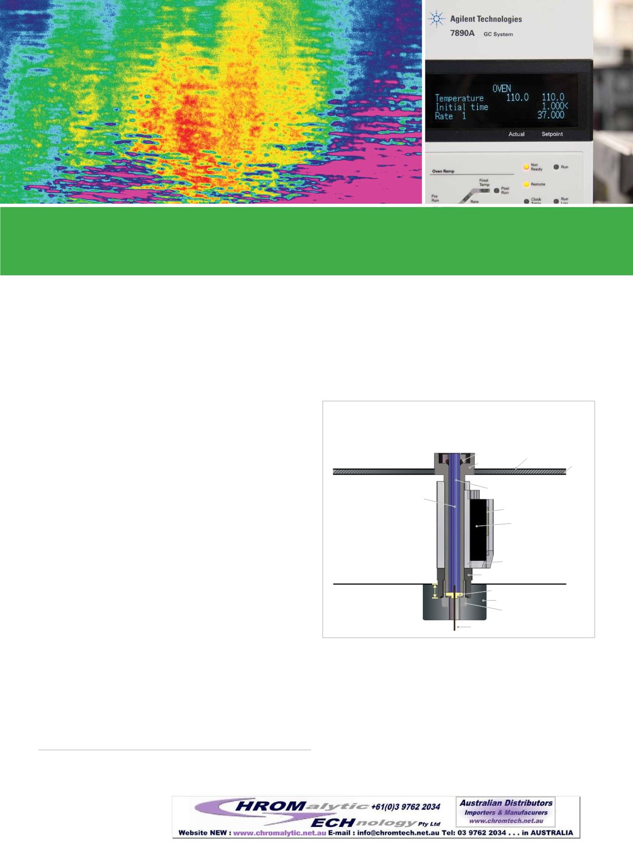
given inlet temperature setpoint. (See Figure 1 to identify the compo-
nents of a GC inlet.) Instead of just measuring the temperature inside
a liner near the O-ring’s location, we used a thermocouple to measure
temperature along the entire length of the liner at a constant inlet tem-
perature setpoint of 250 °C. The resulting thermal profile confirmed that
a temperature gradient exists within the inlet.*
In previous work
(www.restek.com/hotseptum), we also discussed this
gradient within GC inlets and noted that inlet thermal profiles can vary
greatly between manufacturers, but would they vary between similar
inlets from the same manufacturer?We checked another similar inlet to
compare the thermal profiles and found that the second inlet exhibited
a different thermal profile from the first. After measuring several more
Agilent GC inlet temperature profiles, we found inlet-to-inlet variation in
all cases, even in ostensibly identical inlets (Figure 2).
Insulation is Crucial to Minimizing
Temperature Variation
We did observe one split/splitless inlet with significantly lower tempera-
tures at the top and bottom. After investigating, we discovered that
the top ring of insulation, which sits just below the perforated disk of
the Agilent 6890 split/splitless inlet weldment, was missing. Some of
the insulation at the bottom of the inlet, along with the thermal nut,
was also not installed. Simply placing insulation in the top cavity and
installing the thermal nut caused the temperature of the inlet liner to
more closely match the other inlets (Figure 2). This test was a valuable
reminder of the need to carefully reconstruct the inlet whenever the
insulation is disturbed.
It’s AMatter of Degrees, but Do Degrees Really Matter?
An Observation of GC Inlet Temperature Profile and Inlet-to-Inlet Temperature Variability
Figure 1:
Considering how little of the GC inlet is actively heated
by the heating element, it’s no surprise a temperature gradient
exists—especially if insulation is missing from the top or bottom.
Oven
Wall
Open Air
Oven
Column
Reducing Nut
Nut Warmer Cup
Inlet Seal
Thermal Nut
Aluminum
Heater Block
Heating Element
Heater Sensor
Liner
Point of
Injection
O-Ring
Inlet Body
Perforated Disk
Insulation
1.2
cm
* For these experiments, we only measured the thermal profile of the
liner inside the inlet, not the entire inlet.


