


 217 / 298

• 12 •
www.restekcorp.comRESTEK Advantage
800-356-1688
By Gary Stidsen, Innovations Team Manager
Minimize Adsorption of Active
Analytes, Using a Drilled
Uniliner
®
GC Inlet Liner
Now in Two Configurations, to Match
Chromatographic Conditions
✔
Eliminate injector active sites and dead volume—
minimize adsorption and discrimination.
✔
Use one configuration if analytes elute near the solvent peak.
✔
Use alternate configuration if analytes elute later than the solvent.
In sample injections into a hot splitless injection
port liner, a typical 1µL sample expands to a volume
of hundreds of microliters.
1
The sample solvent
vapor, and the analytes, fill the entire injector sys-
tem. Analyte molecules come in contact with hot,
active surfaces outside the injection port liner, and
occupy the dead volume at the bottom of the injec-
tion port, below the inlet end of the column (Figure
1). In splitless injection mode, there is very little
carrier gas flow in this area to carry the analytes
back up to the column inlet. This situation is most
noticeable with active compounds that degrade
when they come in contact with active surfaces;
recoveries can be significantly reduced. In addition,
late-eluting compounds that do not readily vaporize
are affected by injection port discrimination.
The innovative geometry of a Drilled Uniliner
®
inlet
liner minimizes active sites in the sample pathway,
and reduces injection port discrimination. The ana-
lytical column connects to the bottom of a Drilled
Uniliner
®
inlet liner via a Press-Tight
®
seal (Figure
1), eliminating sample contact with any part of the
injector below the column inlet. Recoveries of active
analytes are significantly improved.
2
A hole in the
side of the liner allows the injector to be operated in
traditional split/splitless mode.
We now offer Drilled Uniliner
®
inlet liners in two
configurations (Figure 2). The liner to use depends
on the analysis, and how closely the early-eluting
compounds elute to the solvent peak.
Analytes
contact hot
surface and
dead volume
at base of
splitless
liner
Figure 1
—
Inlet liner geometry affects
analyte recovery.
Drilled
Uniliner
®
inlet liner
efficiently
conveys
sample onto
column
Rtx
®
- 5Sil MS 30m, 0.25 ID, 0.25µm (cat.# 12723)
Sample:
methylene chloride, PR grade
Inj.:
0.5µL, splitless (hold 2.5 min.)
4mm single gooseneck inlet liner
(cat.# 20799)
4mm Drilled Uniliner
®
inlet liner
(cat.# 21055)
4mm Drilled Uniliner
®
inlet liner
(cat.# 20756)
Inj. temp.:
260°C
Carrier gas:
helium, constant pressure
Linear velocity:
17cm/sec. @ 50°C
Oven temp.:
50°C, isothermal
Det.:
FID @ 330°C
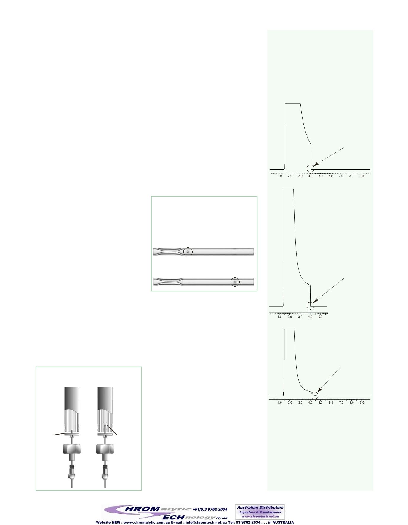
Figure 3
— Solvent peak profiles
from Drilled Uniliner
®
inlet liners and a
splitless liner.
GC_EV00680
3a) 4mm single gooseneck splitless liner
Use hole near top configuration if analytes elute later than
the solvent peak, or when the sample solvent is water
Figure 2
—
Drilled Uniliner
®
inlet liners
are available in two configurations. The hole
allows the injector to be operated in
split/splitless mode.
Use hole near bottom configuration if analytes elute near
the solvent peak
In flash on-column injection all of the solvent is
transferred from the injector to the column, produc-
ing a substantial solvent peak tail. Splitless injection
eliminates the solvent tail, because the injector goes
into the split mode after the compounds of interest
are transferred to the column, and all solvent
remaining in the injection port is flushed out
through the purge vent. The solvent peak ends
abruptly, as shown in Figure 3a. Elimination of the
solvent peak tail is an advantage to using the splitless
injection technique when analyzing compounds that
elute close to the solvent.
A Drilled Uniliner
®
inlet liner produces a distinctly
different solvent peak shape than the single goose-
neck splitless liner, as shown in Figure 3b and
Figure 3c. The most noticeable difference is the
peak width; the peak is considerably narrower than
the peak from the single gooseneck liner. The posi-
tion of the hole in the Drilled Uniliner
®
also affects
solvent peak shape. A Drilled Uniliner
®
with the hole
near the bottom produces a sharply ending solvent
peak, similar to that from a single gooseneck liner
(Figure 3b). This liner is a direct replacement for a
splitless liner, and should be used when analytes
elute closely behind the solvent.
No solvent peak tail
3b) 4mm Drilled Uniliner
®
liner,
hole near bottom
No solvent peak tail,
equivalent to single
gooseneck liner
3c) 4mm Drilled Uniliner
®
liner,
hole near top
Solvent peak tail, from
solvent remaining in liner
The position of the hole in a Drilled
Uniliner
®
inlet liner affects solvent
peak shape.
Continued on page 13