POPULARCONFIGURATIONGCs
CryosulfurGC
General OperatingProcedure
2. Connect your helium source to the carrier
gas inlet on the left-hand side of the GC.
Connectyourhydrogensource to thehydrogen
inlet. Leave the jumper inplace if youplan to
use the built-in air compressor to supply air for the detectors. Otherwise, remove the jumper and
connect your air source to the air inlet on the left control panel.
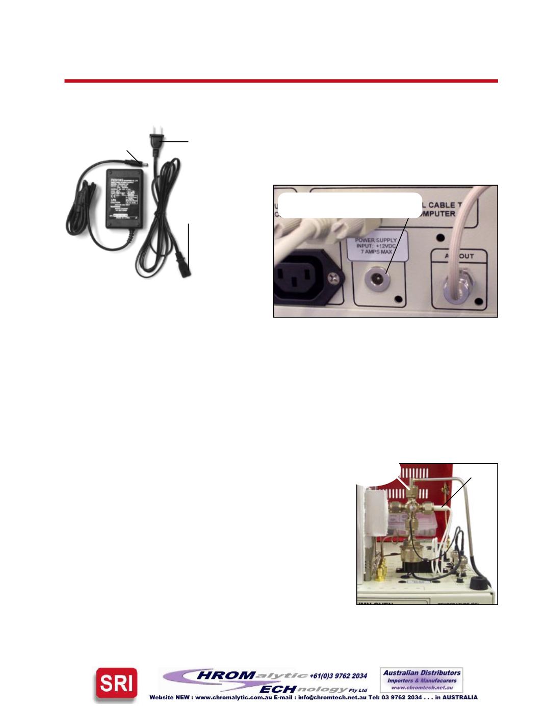
1. Plug theGCpower cord into awall outlet and turn the
main power ON. Plug the CryoCooler into it’s power
source, andplug thepower sourcecord into thewalloutlet.
The CryoCooler power source plugs into the GC chassis
between thevacuumpump interfaceand theAirOut fitting
on the left-hand side of theGC as shown below.
4. Use the switchon theGC front control panel to light thedetector flame (vertically labeled“FLAME
IGNITE” under “DETECTOR PARAMETERS”). Often the
flame can be difficult to light because of the hydrogen-rich
atmosphere inside the detector body. Make sure that thePMT
voltage isOFF (that switch isalsoon theGC frontcontrolpanel,
vertically labeled “PMT VOLTS” under “DETECTOR
PARAMETERS”), then remove the cap nut on the detector
exhaust port. KEEP YOUR FACE AWAY FROM THE
DETECTORWHILE LIGHTINGTHE FLAME, and try the
ignitor switch again. When the flame lights, there will be a
loud noise like the backfiring of a car; this is normal and does
not indicateaproblem. Thenoise is accompaniedbya flashof
flame. Replace the exhaust cap nut after the flame is lit.
3. Set the hydrogen flow to 60-80mLs/minute; this correlates to a flow of 30-40mLs/minute each for
the primary and secondary hydrogen used by the FPD/FID combination detector. Set the air flow to
100mLs/minute. The detector air supply tubing is T’d inside theGC so that 10-30mLs/minute of air
flowsacross the faceof thephotomultiplier (PMT). Thegaspressures required toachieve thesespecific
flows are printed on the right-hand side of theGC.
Ignitor
Exhaust
port cap nut
CryoCooler power source:
Plug this end into
theGC chassis.
Plug this end into
the power source.
Plug this end
into thewall
outlet.
5. Switch ON the PMT voltage and set it at 400-500 by adjusting the appropriate trimpot (“PMT
VOLTAGE” under “DETECTOR PARAMETERS”). The greater the voltage setting, the higher the
FPD sensitivity. The PMT volts were set at 500 for the 10ppbH2S analysis shown on the Expected
Performance page.
Plug the CryoCooler’s power
source into theGC chassishere:


