Quick Start
Model 202
FourChannelPeakSimpleDataSystem
STEP1: Connect theAnalogSignalCable(s)
1-1. Routetheanalogsignalcablesfromyourinstrument
through theopenhole in thebackof theModel202.
1-2. Strip1/4”of insulation from the “signal+” and
“signal-”wiresofyourinstrument’ssignalcables.
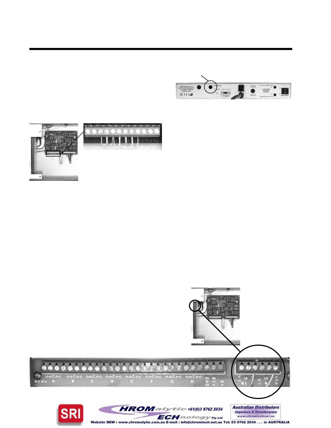
1-3. Remove the jumpersshown in theclose-
uppicture to the left. Insert the“signal+”wire
into the Lawson 202 board screw terminal
marked“CH1sig+”andsecure theconnection
withasmallflat-bladescrewdriver.
1-4. Insert the“signal-”wire into theLawson
202boardscrew terminalmarked“CH1sig -”
andsecure theconnection.
1-5. Repeat theconnectionofsignalcablesfor
channels 2, 3, and 4. Any unused channels
MUSThaveboth inputs jumpered toground.
STEP2: (OPTIONAL) Connect theRemoteStart Cable
TheModel202remotestartcapabilityallowsyou tostart thedatasystembymeansofaswitchclosure. Two
separateremotestartcircuitspermit theuser to individuallystartTIMEBASE1and2of thedatasystem. In
someapplications, thechromatographbeingusedwiththeModel202mayofferaremotestartsignaloutputor
switchclosureoutput thatpermitsstartingan integratororotherdevicewhen theSTARTbutton ispressedon
thechromatograph’son-boardcontrolpanel. Typically, thissignalcanbeused tostart theModel202.
2-1. Routetheremotestartcablefromyourinstrumentthrough
theopenhole in thebackof theModel202.
2-2. Strip1/4”ofinsulationfromthe“+”and“-”wiresofyour
remotestartcable.
2-3. Insertthe“+”wireintotheRELAYboardscrewterminal
marked“#1IN”andsecure theconnection.
2-4. Insert the“-”wire into theRELAYboardscrew terminal
marked“#1G”andsecure theconnection.
Route thesignal cables through thishole
TheModel202 isshipped
with jumpers in the
Channelscrew terminals


