System Overview
12 of 82
•
Easy access for replacement of valves.
•
The Antechamber has a door lifting mechanism so the door lifts gently and cannot close
unless pulled down by the user.
•
Gloveboxes are modular in design; there are no bolts through the end panel or front window
that could cause potential leaks.
•
All connections are stainless steel tubing, which is either welded or connected via KF-40
clamps or compression connectors. There are no rubber hoses or hose clamps which, over
time, can develop leaks or cracks.
.The
GloveBox
control system is PLC-based and has a color HMI touch screen interface
•
This system monitors and controls all box functions. Extensive functionality and user
features are available in the System Controller.
2.1 The PLC Enclosure
The PLC enclosure is located on the front of the gas purification module.
2.2 Exterior Controls
On the PLC enclosure, mounted on the side wall, you will find several circuit breakers and an
illuminated main circuit breaker that doubles as the main power on switch.
2.3 Circuit Breakers
There are seven (7) circuit breakers on the side wall. The function of each breaker is indicated
on a label at the side of the breaker. When they are in the tripped position, a white colored tab
extends from the middle of the breaker. To reset them, press the tab back in until it locks in
place. A label on the inside of the enclosure door contains specific information regarding the
circuit breakers.
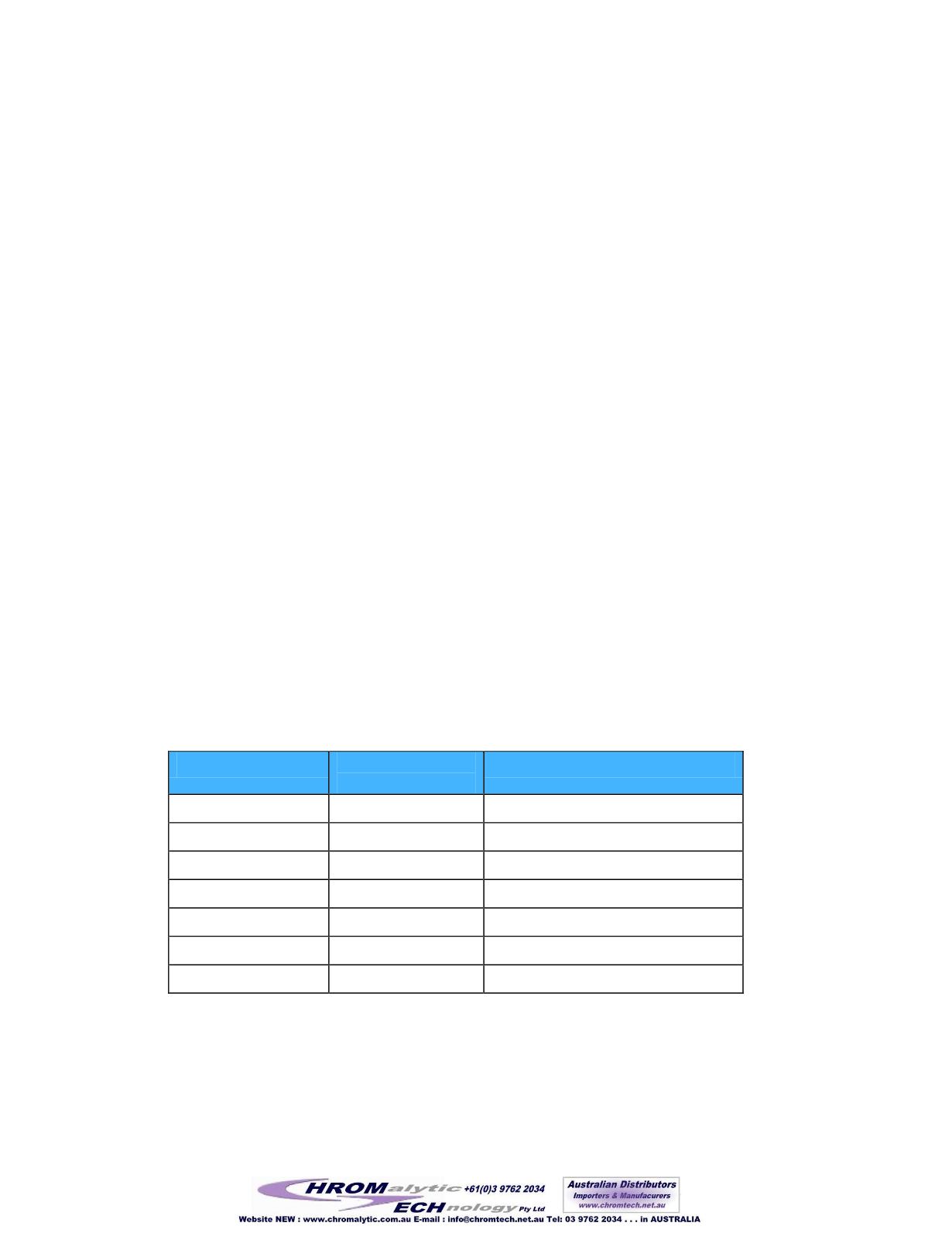
Table 1 Circuit Breakers
Circuit Breaker #
Amperage
110/220 VAC
Function
1
15A/10A
Illuminated Main Power Switch
2
10A/5A
Vacuum Pump
3
6A/3A
24V Power Supply
4
5A/3A
Blower
5
4A/2A
Heater for Column 1
6
4A/2A
Heater for Column 2
7
5A/3A
Lighthood
2.4 Foot Pedal
A foot pedal is provided so that the box pressure can be increased or decreased without the
operator having to remove their arms from the gloves. It is a dual pedal switch. The right pedal
97


