VALVES
127
EffectsofValvesand
TubingonResolution
The effect of tubing on analytical andmicroscale analyses can be
significant. Sincedispersion causedby tubing is proportional to the
fourthpowerofdiameter, largebore tubingshouldbeavoidedwhen
performing analytical scale or microscale analyses. Tubing ID size
≤0.25mm (0.010”) is recommended.
Consider a system with injection and column switching valves
and analytical columns with small-bore connecting tubing. The
chromatogramsbelow,madeusingatypicalanalyticalchromatograph,
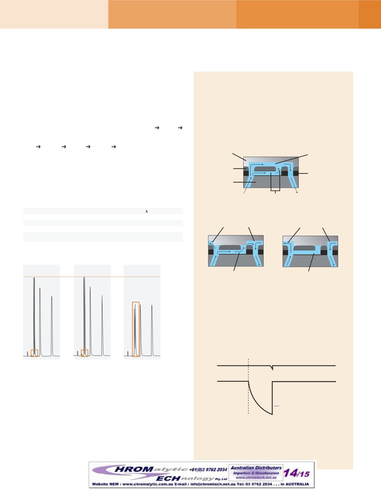
showtheseeffects.SchemeA isthecontrol (injectionvalve column
detector)withnovalve in thesystem. InSchemesBandC, twomodel
7060Six-PositionSwitchingValveswereplacedsidebyside (injection
valve valve#1 column valve#2 detector).
The injection valve anddetector were connected to these valves by
thesame tubingused in thecontrol.Theextra tubingpieces required
to connect the valves to the columnwere a 10 cm length for valve
#1-to-column,anda35cm lengthforcolumn-to-valve#2.Thediameters
of these tubes are indicated in theexperimental details, below.
ComparisonofObservedColumnPlatesof Rheodyne
®
Analytical andMicroScale InjectionValves
Effectsof Valves andTubingonResolution
Conclusion: These sequential chromatograms show the effect of
addingvolume to theflowpath through theadditionof components.
(A) Establishes a baseline quality of separationwith theminimum
volumeof liquid in theflowpath.
(B)Addinga valveplus smaller-ID tubing, and thereby increasing the
liquidvolumeonlymarginally,barelyaffectstheseparation.However in
(C)Addingavalveplus larger-ID tubing, thereby increasing the liquid
volume in the flowpath to a greater degree, distinctly impairs the
qualityof the separationand thedetectable sample.
7725
8125
k’ = 0.6
2930
5054
72%
k’ =1.5
4653
6904
48%
k’ = 7.9
7875
8305
5.0%
UVdetector: 1µLvolume, 4mmpath. Samplevolume: 2µL, partial-fillingmethod.
Column: 2mm IDx100mm long, 4µmC-18. Trueplatesof column=11,570.
What isMake-Before-Break
™
,
andWhenDoes itMatter?
Make-Before-Break isauniquedesign featureof certain
dual-modemanual injection valves.
Flowpathsofmodel 7725(i) and9725(i)withMBBdesign
To maintain a constant, desired high-pressure flow,
Rheodyne’s Make-Before-Break (MBB
®
) design creates
continuous flowbetween the LOAD and INJECTpositions
thatvirtuallyeliminatespressuretransientshocktothesystem.
Apassage in thestator facemakesanewconnectionbefore
oldconnectionsbreak.TheMBBdesign—an improvement
overbypass-style injectors—doesnotdilutethesampleand
iseasy tomaintainand troubleshoot.
MBB valve
Non-MBB valve
Pressure shock
Inject
Pressure
Time
Rotor SealGrooves
MBBPassage
PositionC
Rotor SealGrooves
MBBPassage
PositionB
PositionA
Shaft End
Rotor Seal
Stator
Face
Stator
Rotor SealGroove
Stator FaceSeal
Column
Pump
MBBPassage
A
ColumnOnly
C
Valvew/ 0.020”
Tubing
B
Valvew/ 0.007”
Tubing
ValveOverview


