800-356-1688 or 814-353-1300
107
GC COLUMNS |
PLOT COLUMNS
PLOT Column Select ion
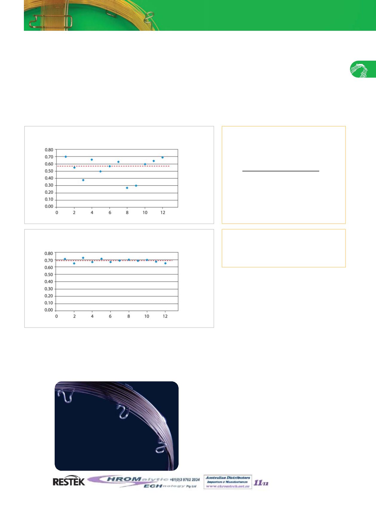
Figure 4
New PLOT columns from Restek offer consistent flow
resistance, giving more reproducible results column-to-column.
In order to evaluate flow restriction reproducibility, Restek is introducing a new factor: the flow restriction factor (F). This factor is
based on the retention time of an unretained marker compound, as measured on both coated and uncoated tubing using the same
backpressure setting (Equation 1). For quality control purposes, methane is used as the marker when evaluating porous polymer
columns and helium is used for testing Rt®-Msieve 5A columns.
Flow restriction factor determination can be used both to assess the degree of column restriction and to evaluate the reproducibility
of the column coating process. Percent flow restriction can also be calculated (Equation 2). Figure 3 shows typical results for PLOT
columns manufactured using a conventional process. Because of the difference in flow restriction, individual columns have very dif-
ferent flow characteristics. In contrast, Figure 4 shows results for columns made using the new PLOT column process (Rt®-QS-
BOND, bonded porous polymer). Clearly, the new manufacturing process results in greater consistency in both column coating
thickness and flow restriction; which, in turn, results in more stable retention times and better performance in Deans switching and
related flow switching techniques.
Equation 1
Flow restriction factor (F) is used to
demonstrate coating consistency.
In summary, Restek’s new PLOT column manufacturing process produces exceptionally robust PLOT columns, featuring concentric
stabilized coating layers. These new columns have more consistent flow resistance and are recommended for applications sensitive to
variation in retention time or flow. These columns are a significant advance in PLOT column technology and are ideal for more effi-
cient, reproducible analyses of permanent gases, solvents, and hydrocarbons.
Equation 2
Percent flow restriction of coated
column.
% restriction = (1 - F) x 100
t
R1
of unretained component
(uncoated tubing)
t
R2
of unretained component
(coated column)
F =
Number of Columns
t
R
= retention time
Note, F values will always be <1 as the coated column
always has more restriction than the uncoated column.
F
Figure 3
Traditional PLOT columns show significant flow variability,
indicating inconsistent column coating thicknesses.
F
Number of Columns
now
available
!
Metal MXT® PLOT Columns
See pages 108-110.
Website :
E-mail :
TelNo : 03 9762 2034 . . . in AUSTRALIA
Mar 2011


