4
An on/off solenoid valve is used in headpressure-regulated systems instead of the 3-way
solenoid valve used in backpressure-regulated systems. The position of the solenoid valve
determineswhether the injection port is operated in the split or splitless injectionmode. In
the split injectionmode, the solenoid valve is always in the open position and the carrier gas
is allowed to flow through the injection port liner and out the split vent line. In the splitless
injectionmode, the solenoid valve is closed and the only flow through the injection port
liner is the column flow. The pressure regulator compensates for excess carrier gas flow
availablewhen the solenoid valve closes.
The throttling valve upstream from the pressure regulator (Figure 2) is an optional compo-
nent not typically included by the chromatographmanufacturer.We recommend installing a
throttling valve (flow controller or needle valve) to guard against catastrophic loss of carrier
gas if a leak occurs at an injection port fitting or a column fitting. To adjust the throttling
valve, gradually close the valve, reducing the gas flow until it matches the requirements of
the injection system.When the column headpressure begins to decrease, the throttling valve
is closed too far.
Operating in the Split InjectionMode
When operating in the split injectionmode (Figures 1 and 2), the solenoid valve is always
open along the flowpath from the injection port body to the split vent.With the exception of
the septum purge flow, all of the carrier gas entering the injection port flows through the
injection port liner and toward the head of the column.At the head of the column, the carrier
gas flow is split between two flow paths: a portion of the flow enters the column as the col-
umn flow rate, and the remaining carrier gas flow is allowed to escape from the injection
port, out the split vent line via the solenoid valve. The amount of flow entering the column
is determined by the pressure of the carrier gas inside the injection port and the dimensions
of the analytical column. The relative proportions of the split vent flow and the column flow
determine the split vent ratio.
Samples completely vaporized in the injection port liner behave in the same fashion as the
carrier gas; sample vapors are split in the same proportions as the carrier gas, thereby allow-
ing only a fraction of the sample to be introduced into the head of the column.A 50-to-1
split ratio can be used as a starting point when developing split injectionmethods. Table I
shows the appropriate split vent flow rates for helium and hydrogen carrier gaseswhen
using common capillary column IDs.
Equation 1 shows how the split ratio is calculated. Split vent flow rates easily can bemeasured
using a standard electronic flowmeter (cat.# 21622). However,measuring low flow rates (from
0.3 to 5cc/min.) exiting a capillary column can be difficult unless a special low-volume bub-
blemeter (cat.# 20135) or a sensitive electronic flowmeter is used. If a low flow-measuring
device is not available, Equation 2 can be used to determine the approximate column flow.
Calculating the on-column concentration of analytes is necessary to ensure that the column
is not overloaded and is operatingwithin its capacity limits.Although quantitative analysis
does not require that the on-column concentration be known, exceeding column capacity
decreases resolution and reduces quantitative accuracy. Equation 3 illustrates how to calcu-
late the approximate on-column concentration in the split mode.
Setting the injection port temperature properly is critical for obtaining good peak shape and
response. Injection port temperaturemust be hot enough to provide rapid vaporization of all
Table I.
Typical split vent flow rates for 50-to-1 split ratio at optimum linear velocitywhen using
a 30-meter column at 40°C.
Column ID (mm)/SplitVent FlowRate
CarrierGas
0.18
0.25
0.32
0.53
helium*
25cc/min.
37.5cc/min.
55cc/min.
135cc/min.
hydrogen**
50cc/min.
75cc/min.
110cc/min.
270cc/min.
*optimum carrier gas linear velocity=20cm/sec.
**optimum carrier gas linear velocity=40cm/sec.
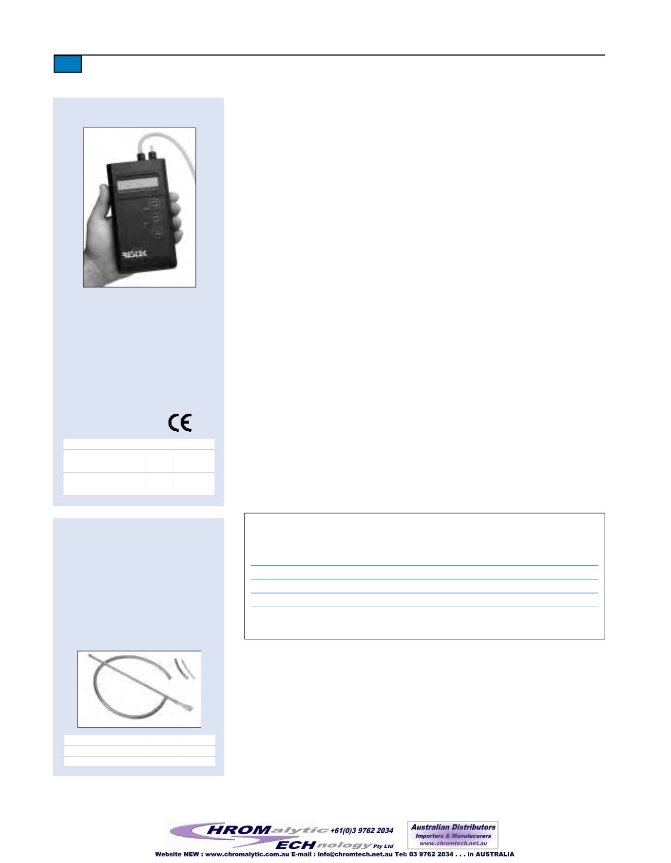
Restek Flowmeter 6000
• Calculates linear velocitybasedon col-
umn ID.
• Useful formeasuring flows forN
2
, air,
He,H
2
, CO
2
,O
2
,Ar, 7.5%CH
4
/Ar.
• Reads flow accurately from0 to
500mL/min.
(0–300mL/min. forCO
2
)
.
• Accuracy is 0.2mL/min. or +/- 2.5%.
• Usablewith inlet pressures up to25psi.
• Measures split flow and calculates split
ratio.
• Automatic shut-off.
Description
qty.
cat.#
Restek Flowmeter 6000
(9-volt battery-operated)
ea.
21622
Recalibration Service for
Restek Flowmeter 6000 ea.
24618
Soap FilmBubble Flowmeters
• 1mL flowmeter measures flows
between 0.1 and 10cc/min.
• 50mL flowmeter designed for flows
between 10 and 300cc/min.
• Both flowmeters come with a reser-
voir bulb, twenty-four inches of
1
/
4
-inch ID tubing, adaptor tubes for
1
/
8
-inch tubing and 0.53mm ID capil-
lary columns, andVelcro
®
fasteners.
Description
qty.
cat.#
1mL Bubble Flowmeter
ea.
20135
50mL Bubble Flowmeter
ea.
20136


