3
Figure 1.
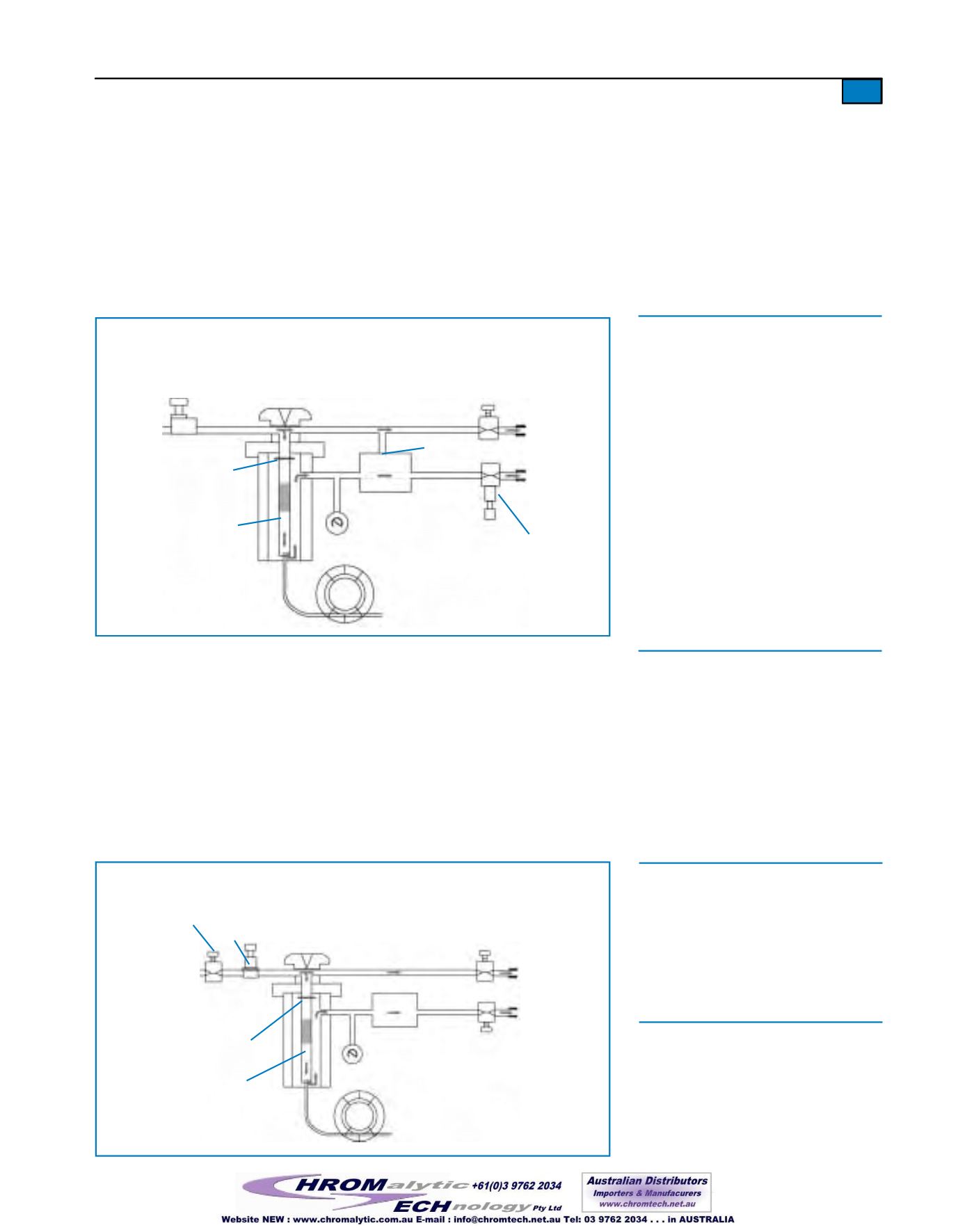
Split injection flowpaths in a typical flow-controlled/backpressure-regulated system.
flow controller
carrier gas
inlet
injection
port
o-ring or
ferrule
injector
liner
3-way solenoid
valve
needle
valve
septum
purge vent
split vent
backpressure
regulator
to detector
closed
A flow-controlled, backpressure-regulated system is beneficial as it gives somemeasure of
protection against a catastrophic loss of carrier gas. If there is a leak at an injection port fit-
ting or a column fitting, themaximum rate of carrier gas losswould be the total flow rate
into the injection port as determined by the flow controller. Unlimited flow of carrier gas
into the injection port is prevented by having the flow controller at the inlet of the injection
port. Leaks are indicated by a failure tomaintain split vent flow rate.A commonmistake
analystsmakewhen they observe a reduced split vent flow is to increase the total system
flow, rather than check for leaks at the injector and column fittings. By understanding the
characteristics of backpressure regulated pneumatics, analysts can detect and correct a leak,
to avoid poor chromatography.
analytical
column
Figure 1.
• All carrier gas except septum purge
flow directed through injector.
• Column flow (established by backpres-
sure regulator) enters column.
• Solenoid valve open from injector to split
vent. Bulk of gas flows out of injector
liner, through solenoid valve, out split
vent.
• Sample vapor is directed onto column or
vented through split vent and is split in
the same proportions as for carrier gas.
• Split ratio = portion of sample vented
from split vent/portion of sample that
enters column.
Headpressure-Regulated Injection Systems
Figure 2 illustrates the components of a typical headpressure-regulated split/splitless injec-
tion system (e.g., PEAutosystem; Shimadzu 9A& 14A; Thermo FinniganTrace 2000
GCs).A pressure regulator upstream from the injection port regulates ormaintains the pres-
sure inside the injection port. The pressure regulator supplies an unlimited flow of carrier
gas until the desired pressure is reached. The pressure inside the injection port establishes
the carrier gas flow in the column and determines the column flow rate. Flows through the
split vent line and the septum purge line are controlled by needle valves or restrictors down-
stream from the injection port. The outlet pressure of the septum purge and split vent lines
is ambient pressure.As long as constant pressure ismaintained in the injection port, needle
valves and restrictorswill give constant flows.
Figure 2.
Split injection flowpaths in a typical headpressure-regulated system.
throttling valve
(optional safety
device)
carrier inlet
injection port
o-ring or
ferrule
injector
liner
solenoid
valve
needle
valve
septum
purge vent
split vent
pressure
regulator
needle
valve
to detector
column
open
Figure 2.
• Solenoid valve open: column flow passes
into column, split flow exits through split
vent.
• Throttling valve guards against loss of
carrier gas caused by leaks in injection
system.


