Basic HTML Version


Trademarks:
Kel-F
®
is a registered trademark of the 3M Company
PEEK
TM
is a trademark of Victrex plc
Rev. 0205
Sample Injection Valve
1106
•
Allows introduction of reproducible sample
volumes
•
0.5ml, 1.0ml and 2.5ml sample loops included
Designed for low pressure chromatography systems, this loop
injection valve sytem is supplied with 0.5ml, 1.0ml and 2.5ml
loops and a 5ml syringe. Other loops can be supplied on
request. A clamp for easy mounting to a retort stand is
included.
See application notes below.
Part
Number
Description
Pack
Size
1106
Manual sample injection valve
1
1106.5 Spare sample loop for use with 1106 0.5ml
1
1106-1 Spare sample loop for use with 1106 1ml
1
1106-2 Spare sample loop for use with 1106 2.5ml
1
1106-5 Spare sample loop for use with 1106 5ml
1
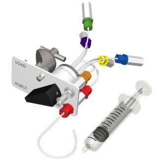
The images below show Omnifit loop inject valves in use as sample injection devices in a chromatography system. These are
the most common applications but the use of the valves is not limited to these.
Application and set up notes.
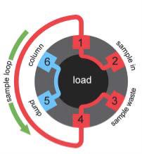
6 port loop inject valve used as a sample injector
With the valve in the load position the sample can be injected into the
sample loop while the mobile phase is pumped directly through to the
column.
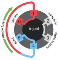
When the valve is switched to the inject position, the pump is then con-
nected to the sample loop and the sample is carried onto and through the
column. The ‘sample in’ and ‘waste’ ports are joined but isolated from the
loop.
It is suggested that ports are connected to the corresponding lines as
shown. This ensures that the flow of the mobile phase is in opposite direc-
tions during the load and inject operations.
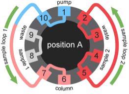
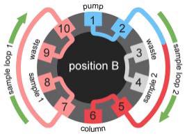
10 port loop inject valve used as a sample injector
This valve allows alternate injection from two different sample loops, either
identical or of different sizes. This application can alternatively be satisfied
with a 4 port switching valve and a 6 port loop inject valve.
With the valve in position A, sample 2 can be loaded into sample loop 2
while the mobile phase is pumped through sample loop 1 and carries
sample 1 onto the column. The ‘sample 1 in’ and ‘waste’ ports are con-
nected but isolated from the loop.
When the valve is switched to position B, the pump is connected to sample
loop 2 and sample 2 is carried onto and through the column. The ‘sample 2
in’ and ‘waste’ ports are connected but isolated from the loop. Whilst sample
2 is pumped onto the column, sample loop 1 can be re-loaded.