11
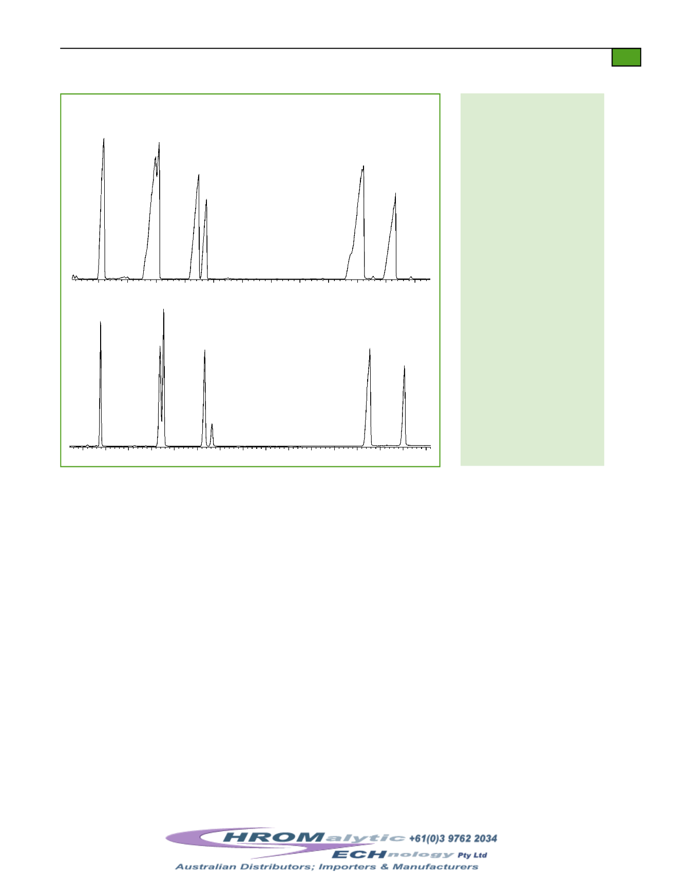
Figure4a&4b.
Avoidoverloadby selecting a columnwith theproper capacity.
1
2
3
4
5
6,7
8
1
2
3
4
5
6,7
8
Peak List for Fig. 4a& 4b
1. di-
n
-octyl phthalate
2. benzo(b)fluoranthene
3. benzo(k)fluoranthene
4. benzo(a)pyrene
5. perylene-d12
6. indeno(1,2,3-cd)pyrene
7. dibenz(a,h)anthracene
8. benzo(ghi)perylene
4a
Poor peak shape for a
0.25mm ID, 0.25µm
Rtx
®
-5SilMS column
4b
Excellent peak shape for a
0.25mm ID, 0.5µm
Rtx
®
-5SilMS column
to-separate analytes, sharing commonmass spectra andquantitation ions. Figure5 shows a
80ngper component injectionof the compounds listed inTable Iwith an analysis time under
30minutes. The expanded sections of the chromatogram show the excellent resolution that
canbe achievedwith theRtx
®
-5SilMS column.
In the past, theGC/MS systems used for semivolatile analysis didnot have the sensitivity for
split injections, so laboratorieswere limited to splitless injection.Newer systems such as the
Agilent 5973 and ion trapGC/MShave greatly improved sensitivity,which allow the use of
split injection
and stillmeet the detection limits requiredbymost semivolatilemethods.
Figure 6 shows the 20ngper component standard injected in splitmode using a 20:1 split ratio
on a 30m, 0.25mm ID, 0.25µmRtx
®
-5SilMS column. The lowbleed exhibitedby this
column is criticalwhenworkingwith thesemore sensitiveGC/MS systems.Abenefit of split
injection is narrower peakwidths for improved separations between closely eluting com-
pounds.Also, split injections usually result in less reactive compoundbreakdownbecause the
residence time in the injectionport ismuch shorter than in splitless injection.
If the sensitivityof an instrument allows for split injection, then column capacity is not nearly
the issue it is for splitless injection. Figure 7 shows a 160ng-per-component standard injected
under the same conditions as shown inFigure 6.Acolumnwith a thinner film canbe used
because the concentration reaching the column is reducedby20-fold. The analytical system
using split injectionwill be able tohandlehigher concentrations of contaminants andpossibly
stay calibrated longer, but therewill be a sacrifice inmethoddetection limits (MDLs).
Therefore, it is important to ensure that theMDLs specified in a particularmethod still canbe
met if split injection is used.
18.5 16.0 16.5 17.0 17.5 18.0 18.5 19.0 19.5 20.0 20.5
min.
18
19
20
21
22
23
24
min.
Conditions for Fig. 4a
30m, 0.25mm ID, 0.5µmRtx
®
-5SilMS
(cat.#12738)
160ng splitless injectionof CLP
standard;
GC:
HP/Agilent 6890w/ 5973
mass selective detector, scan range 35-
550AMU;
Ovenprogram:
40°C(hold2
min.) to290°C@20°C/min. (hold0
min.) to303°C@2°C/min. (hold0min.)
to 330°C@ 6°C/min. (hold 1min.);
Carrier gas:
He@1.0mL/min. constant
flow;
Inj. temp.:
300°C;
Det. temp.:
280°C
Conditions for Fig. 4b
30m, 0.25mm ID, 0.25µmRtx
®
-5SilMS
(cat.#12723)
unknown concentration (>160ng)
splitless injectionof CLP standard;
GC:
HP/Agilent 6890w/ 5973mass
selective detector, scan range 35-550
AMU;
Ovenprogram:
40°C (hold2min.)
to 245°C@ 25°C/min. (hold 0 min.) to
330°C@6°C/min. (hold5min.);
Carrier
gas:
He@ 1.0mL/min. constant flow;
Inj. temp.:
300°C;
Det. temp.:
280°C
Website :
E-mail :
TelNo : 03 9762 2034 . . . inAUSTRALIA


